|
微波射频仿真设计 |
|
|
微波射频仿真设计 |
|
| 首页 >> Ansoft Designer >> Ansoft Designer在线帮助文档 |
|
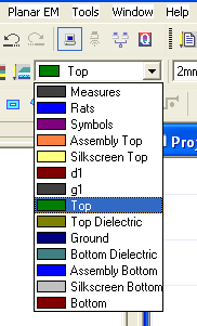
Getting Started with Ansoft Designer > Draw the Model1. Make sure that the active layer is set to “Top”: • If necessary, on the Layout toolbar, select “Top” from the list of layers:
2. Draw a rectangle: a. Do either of the following: • On the Draw menu, point to Primitive, and then click Rectangle. • On the Layout Draw toolbar,
click the Draw Rectangle icon Then in the Layout grid, hold the left mouse button and drag the cursor to create a rectangle and left click to finish. b. Next, use the keyboard to enter the geometry of the rectangle. Double-click in the X coordinate field of the Status Bar (located at the bottom of the Designer screen) and enter 0.0. Then use the TAB key to move to the Y coordinate field and also enter 0.0, then press Enter. Note that the TAB key switches between fields, while pressing Enter commits the data to the design. Also note that the rectangle has now been repositioned to the center of the grid per the 0.0 values for the X and Y coordinates.
c. Should the Status Bar ever appear empty of values when a rectangle or other shape is visible in the Layout, simply left click on the shape to display its Status Bar coordinates. d. Next, complete the rectangle by entering the values of 20 for Delta X and 4.6 for Delta Y, and then press Enter. With each change to the fields in the Status Bar, the rectangle is adjusted according. As an alternative to manually entering values in the Status Bar, you can click and drag to reposition and resize the rectangle. Designer captures mouse movements and automatically updates the Status Bar fields to reflect the changes. Try repositioning and resizing the rectangle. 3. Next, fit the drawing to the Layout window by doing either of the following: • Press CTRL +D. • On the View menu, click Fit Drawing. 4. Now, draw another rectangle: a. Click the Draw Rectangle icon b. Left click to select the lower-right corner of the first rectangle and enter Delta X = 2.1 and Delta Y = −10.5, and then press ENTER. 5. Draw a third rectangle (here we show how to enter the coordinates directly): a. Click the Draw Rectangle icon b. In the status bar, enter 21.05 for X and 0.0 for Y, and then press ENTER. c. Enter 21.7 for Delta X and 0.7 for Delta Y, and press ENTER. 6. Draw a polygon: a. Press the zoom icon or hold SHIFT+ALT and move
the mouse until the minor divisions of the grid become visible. Click
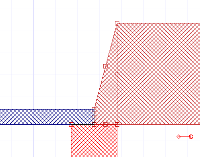
the Draw Polygon icon b. Snap the cursor to the upper-right corner of the first rectangle (20.0, 4.6). Note: If you let the mouse hover briefly over the target point, you will see the cursor jump to the snap point. c. Click the upper-left corner of the third rectangle (21.05, 0.7). d. Click the lower-left corner of the third rectangle (21.05, 0). e. Double-click the lower-right corner of the first rectangle (20.0, 0). f. Press CTRL+D to fit the drawing in the Layout window. At this point, your layout should look similar to the following:
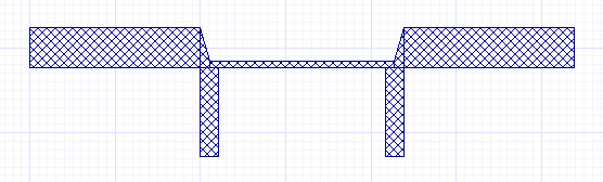
The fill pattern within the objects may be different. 7. Copy and paste the elements: a. Select the polygon, first rectangle, and second rectangle by pressing and holding CTRL while clicking the three objects in turn. b. Next, copy the selected objects by pressing CTRL+C. Then click in the Layout window and press CTRL+V to paste the objects into the layout, as shown.
8. Now, mirror and move the elements that you just pasted: a. Make sure that all of the copied elements are still selected. b. On the Layout Edit toolbar, click the
Flip Horizontal (Flip about Y) icon c. Move the mirrored objects so that they snap
to the lower-right corner of the third rectangle.
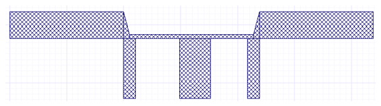
d. Press CTRL+D to view the full geometry, which should now look similar to the following:
9. Draw the fourth rectangle: a. Click the Draw Rectangle icon b. In the status bar, enter 29.3 for X and 0.0 for Y, and then press ENTER. c. Also in the status bar, enter 5.3 for Delta X and−10.5 for Delta Y, and then press ENTER. d. At this point, your layout should look similar to the following:
Save the project: 1. On the File menu, click Save. 2. Type planarEM1 in the File name box, and then click Save.
HFSS视频教程 ADS视频教程 CST视频教程 Ansoft Designer 中文教程 |
|
Copyright © 2006 - 2013 微波EDA网, All Rights Reserved 业务联系:mweda@163.com |
|


 or on the Draw menu, click Flip Horizontal.
 and drag a box around
the portion of the layout you want to magnify.
and drag a box around
the portion of the layout you want to magnify.