|
微波射频仿真设计 |
|
|
微波射频仿真设计 |
|
| 首页 >> Ansoft Designer >> Ansoft Designer在线帮助文档 |
|
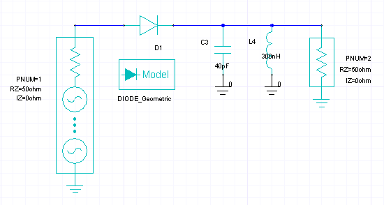
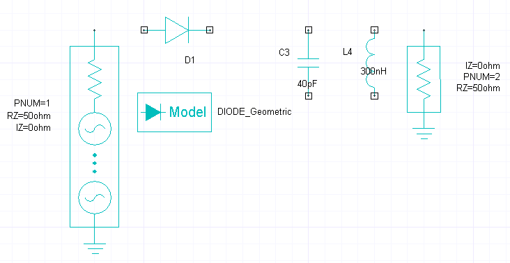
Getting Started with Ansoft Designer > Create the Simple Mixer with the Schematic EditorInstead of opening the example on file, you can use Designer’s Schematic Editor to create the mixer schematic for simulation. We shall create the following circuit.
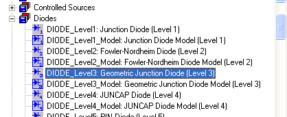
A mixer typically multiplies sinusoidal signals of different frequencies, achieving frequency translation. In this example, input port Port 1 includes two power sinusoidal sources. The lower frequency FLO (for Local Oscillator) acts as a carrier, modulated by the higher frequency FRF. The voltage at Port 2 can be viewed in the time domain. To create the design, follow these steps: 1. Start Designer. A new project, Projectn, should appear (n is the order in which the project was added to the current session of Designer). 2. If no project appears, create one. On the File menu, click New. A new project named Projectn is added to the project tree. 3. Select the project in the Project window. Right-click the project and select Rename from the menu. Our example has been renamed to SimpleMixer. 4. On the Project menu at the top of the Designer window, click Insert Circuit Design. 5. The Choose Technology dialog opens. Click None. This design does not use a physical substrate. 6. The Schematic Editor window opens with an empty design window. 7. Click the Components tab in the Project Manager window. Scroll down to and expand the Diodes folder by clicking on the “+” sign.
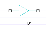
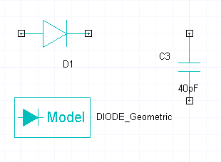
8. This circuit uses the Level 3 geometric diode model. Click on the DIODE_Level3: element, hold down the mouse key and drag the diode symbol into the design window. Press Enter to drop the symbol.
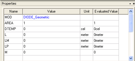
The reference designator Dn is automatically assigned. The n is incremented each time a component is added to the design. 9. Click on the diode symbol to display its properties. .
10. Set the MOD
property to a unique name. We have used DIODE_Geometric. 11. Click on the DIODE_Level3_Model: element, hold down the mouse key and drag the diode model symbol into the design window. Locate the model symbol right below the diode symbol. Press Enter to drop the model symbol. 12. Click on the diode model symbol to display its properties in the Property panel. Set the ModelName property to DIODE_Geometric. Set the IS property (saturation current) to 1e-11 (amperes).
13. In the Components panel expand the Capacitors folder. Click on the CAP_: element and drag the capacitor symbol into the design window. Locate the capacitor to the right of the diode. Press Enter to drop the capacitor symbol. 14. Select the capacitor symbol to display its properties. Set the C property to 40pF. 15. With the capacitor symbol still selected, press CTRL-R to rotate the symbol into a vertical position. Move the capacitor symbol so that its upper terminal is aligned with the output of the diode. The schematic so far should look like:
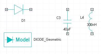
16. In the Components panel expand the Inductors folder. Click on the IND_: element and drag the inductor symbol into the design window. Press Enter to drop the capacitor symbol. 17. Select the capacitor symbol to display its properties. Set the L property to 300nH. 18. With the inductor symbol still selected, press CTRL-R to rotate the symbol into a vertical position. Position the inductor symbol to the right of the capacitor. The schematic so far should look like:
19. At the upper right of the Designer window, click on the Interface port icon
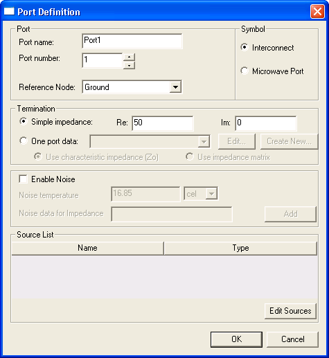
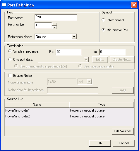
Place one port to the left of the existing elements, and a second port to the right. In our example, the input port is Port 1 and the output port is Port 2. 20. Right-click on the input port and select Edit Port from the menu. The Port Definition dialog opens:
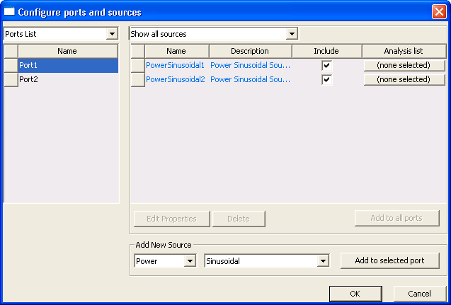
21. Select the Microwave port symbol. 22. Accept thedefault termination of 50 ohms. 23. Click the Edit Sources button. The Configure ports and sources dialog opens:
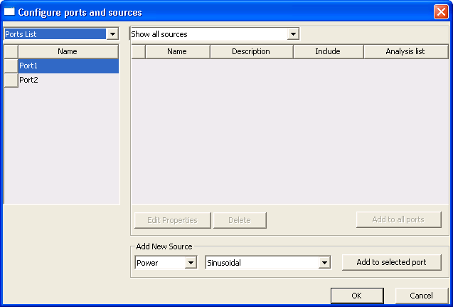
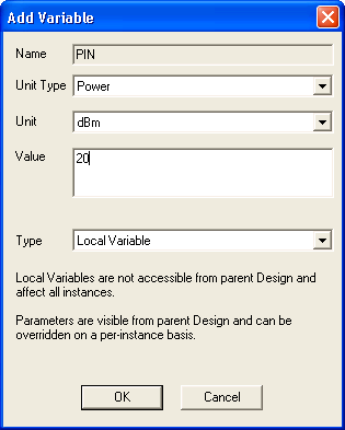
24. Port 1 is selected in the Ports List. Power and Sinusoidal are the default source parameters. Click Add to selected port to add a new power sinusoidal source to the port. The Properties window for the source opens. The three properties of interest are the POWER, FREQ, and TONE parameters. We shall use local variables for the power and frequencies of the sources, making it easier to modify these parameter values between simulations. 25. Set the POWER property to PIN. The Add Variable dialog opens:
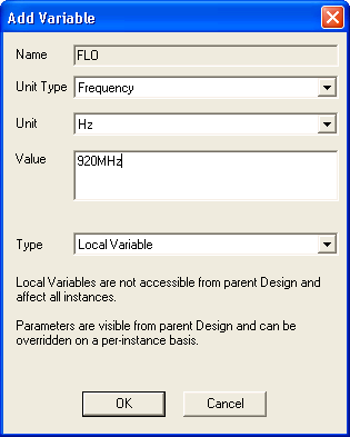
Set the Unit Type to Power, the Unit to dBm, and the Value to 20 as shown. Click OK. 26. Set the FREQ property to FLO. The Add Variable dialog opens:
Set the Unit Type to Frequency, the Unit to Hz, and the Value to 920MHz as shown. Click OK. 27. Set the TONE property to FLO as well. This property is used by harmonic balance. The Properties window for the Power Sinusoidal1 source should look like:
Click OK to close the Properties window. A dialog opens to assign the source to analyses. Dismiss this dialog for now. We shall return to it after we have set up the simulations. 28. Click Add to selected port again to add
a second power sinusoidal source to 29. Set the POWER property to PIN. 30. Set the FREQ property to FRF. The Add Variable dialog opens:
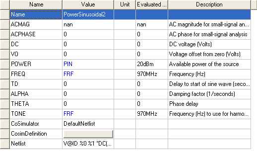
Set the Unit Type to Frequency, the Unit to Hz, and the Value to 970MHz as shown. Click OK. 31. Set the TONE property to FRF as well. This property is used by harmonic balance. The Properties window for the Power Sinusoidal2 source should look like:
Click OK to close the Properties window. A dialog opens to assign the source to analyses. Dismiss this dialog for now. We shall return to it after we have set up the simulations. The Port 1 Configure ports and sources dialog should look like the following:
Click OK to close the Configure ports and sources dialog. The completed definition for Port 1 should look like the following:
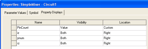
Click OK to close this dialog. 32. Right-click on Port 2 in the schematic, and select Edit Port. Select Microwave port for the symbol type, then click OK. 33. Optional: To relocate the Port 2 property displays as we have done, right-click the symbol and select Properties from the menu. In the Properties window, select the Property Displays tab. On the properties iz, pnum, and rz, use the Location pulldown to select Right as shown below, then click OK to close this dialog.
34. The schematic should look like the following at this point:
35. From the upper right corner of the designer window, click on the Ground symbol and place grounds on the lower terminals of the capacitor and the inductor. The grounds connect to the terminals automatically. 36. Click the output terminal on Port1 to start a wiring operation. A big X appears and a wire is attached to the cursor. Drag the cursor with the wire and connect Port 1 to the input of the diode. Click again to drop the wire. 37. Connect the output of the diode to the upper terminal of the capacitor. 38. Connect the upper terminal of the capacitor to the upper terminal of the inductor. 39. Connect the upper terminal of the inductor to Port 2. The schematic should look like the completed design shown at the beginning of the topic. 40. On the Designer File menu, click Save. A window opens, allowing you to specify the directory where you want to save your work, and the name for your design (the design is saved with a .adsn suffix). The next step is to set up and run Nexxim transient and harmonic balance analyses.
HFSS视频教程 ADS视频教程 CST视频教程 Ansoft Designer 中文教程 |
|
Copyright © 2006 - 2013 微波EDA网, All Rights Reserved 业务联系:mweda@163.com |
|