|
微波射频仿真设计 |
|
|
微波射频仿真设计 |
|
| 首页 >> Ansoft Designer >> Ansoft Designer在线帮助文档 |
|
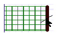
Getting Started with Ansoft Designer > Assign the Ports
1. Create Port1: a. On the menu bar, click Edit, and then click Select Edges. Alternatively, on the Layout Draw toolbar,
click the Select Edges icon b. Point the cursor to the left edge of the first rectangle and click.
c. Click Draw > Port > Create. Note that Port1 appears in the layout editor. Also, in the Project Manager, an icon labeled Port1 appears under Excitations. d. Alternative way to add an excitation (port): First select the edge and, in the Project Manager, right-click Excitations and then click Add Port.
2. Create Port 2: a. Point the cursor to the right edge of the right-most rectangle, and click.
b. Click the Create Edge Port icon, located
on the Layout Draw toolbar.
3. Rename Port 1: a. In the Project Manager, expand the project PlanarEM1: Excitations, then right-click Port1. b. Click Rename, enter p1, and then press ENTER.
4. Rename Port 2: a. In the Project Manager, expand the project PlanarEM1: Excitations, then right-click Port2. b. Click Rename, enter p2, and then press ENTER.
HFSS视频教程 ADS视频教程 CST视频教程 Ansoft Designer 中文教程 |
|
Copyright © 2006 - 2013 微波EDA网, All Rights Reserved 业务联系:mweda@163.com |
|
 .
.