|
微波射频仿真设计 |
|
|
微波射频仿真设计 |
|
| 首页 >> Ansoft Designer >> Ansoft Designer在线帮助文档 |
|
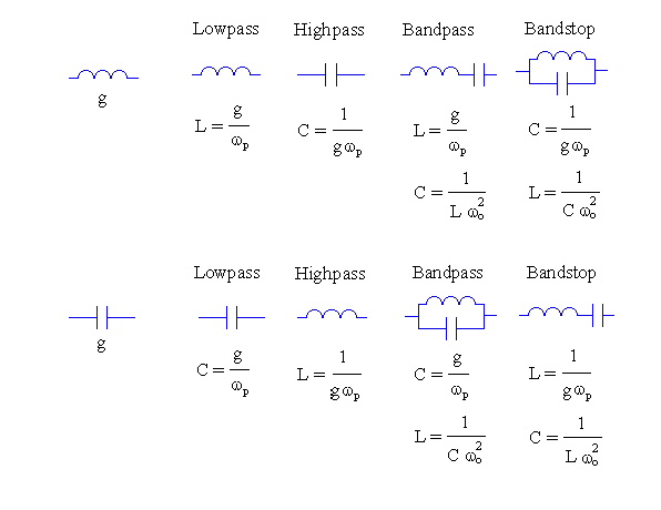
Filter Design Tool > Mapping for Lumped Element FiltersInductor and capacitor lowpass prototype elements are transformed into the following elements when the passband is mapped from the prototype:
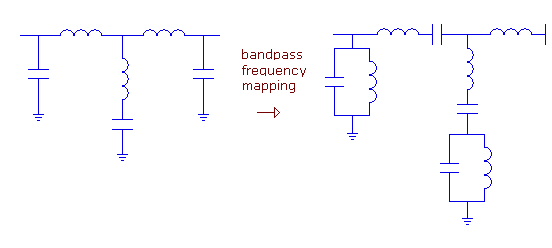
 An example is given below. Notice the middle element: while it is a finite transmission zero in the form of an LC-resonator in the lowpass prototype, it transforms into a “fourth-order section” after the bandpass mapping. These sections bring realizability problems so they are usually replaced by two shunt LC-resonators.
HFSS视频教程 ADS视频教程 CST视频教程 Ansoft Designer 中文教程 |
|
Copyright © 2006 - 2013 微波EDA网, All Rights Reserved 业务联系:mweda@163.com |
|