淘宝官方店     推荐课程     在线工具     联系方式     关于我们  


微波射频仿真设计   Ansoft Designer 中文培训教程   |   HFSS视频培训教程套装


Agilent ADS 视频培训教程   |   CST微波工作室视频教程   |   AWR Microwave Office

          首页 >> Ansoft Designer >> Ansoft Designer在线帮助文档


Ansoft Designer / Ansys Designer 在线帮助文档:


Filter Design Tool >
   Technical Notes >
       Design of Ideal Lumped and Distributed Element Filters >
           Design Example >
               Frequency Mapping and Impedance Renormalization                   


Frequency Mapping and Impedance Renormalization

Choosing 0.1 dB Chebyshev and Rs=Ro prototype, and 90-110 MHz corners, mapped to a bandpass filter. The element values are listed in table below.


[spacer]


Normalized

Renormalized

Rs

1.0

50

L1

9.1262

456.31 nH

C1

280.358

5.607 pF

L2

0.2345

11.72 nH

C2

10911.74

218.23 pF

L3

15.717

785.84 nH

C3

162.795

3.256 pF

L4

0.2345

11.72 nH

C4

10911.742

218.23 pF

L5

9.1262

456.31 nH

C5

280.358

5.607 pF

Ro

1.0

50


The completed filter schematic is given below.


HFSS视频教学培训教程 ADS2011视频培训教程 CST微波工作室教程 Ansoft Designer 教程

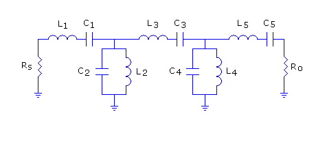
                HFSS视频教程                                      ADS视频教程                               CST视频教程                           Ansoft Designer 中文教程


      Copyright © 2006 - 2013   微波EDA网, All Rights Reserved    业务联系:mweda@163.com