|
|
|
| 首页 >> CST教程 >> CST2013在线帮助系统 |
Bend Sheet or Thin Shape
|
|||||||||||||||||||||||||||||||||||||||||||||||||||||||||||||||||||||||||||||
|
|
Bend Shape |
|
Please note: For multiple selected sheets or shapes it is necessary that all sheets or shapes lie in the same plane, and at least one sheet or shape lies on the surface of the solid.
Bend sheet on cylinder or cone
Bend sheet on a solid that consists of a not developable surface
Bend a printed-circuit board (PCB) design with thick layers on a solid
|
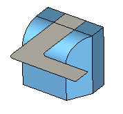
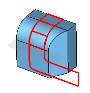
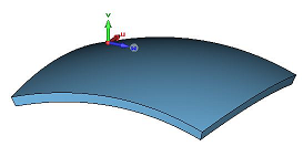
1. Step: Select sheet to bend
|
2. Step: Select solid to bend on |
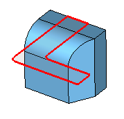
3. Step: Select face to bend on |
|
|
|
|
|
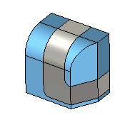
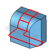
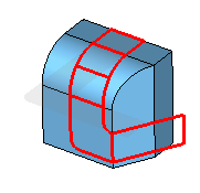
4. Step: Select the next face to bend on |
5. Step: Select the next face to bend on |
6. Step: Finish the bending operation by pressing RETURN |
|
|
|
|
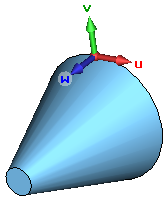
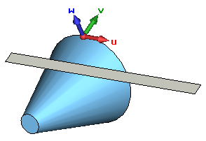
Example: Bend sheet on cylinder or cone
Note that the bending might not work if the sheet intersects the solid.
To ensure that the sheet is placed correctly on the solid, follow the next steps.
|
1. Step: Align the local wcs on a point on the solid |
2. Step: Pick the cylindrical or conical surface |
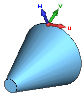
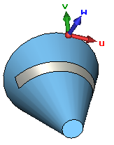
3. Step: Align wcs on the picked face |
|
|
|
|
|
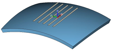
4. Step: Create or align your sheet in the u-v-plane |
5. Step: Bend the sheet on the solid as explained in the previous example |
|
|
|
|
|
To display the poles of the sphere, you may use View
![]() View Options
View Options ![]() Specials (
Specials (![]() ) and check Draw
surface mesh.
) and check Draw
surface mesh.
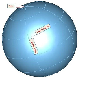
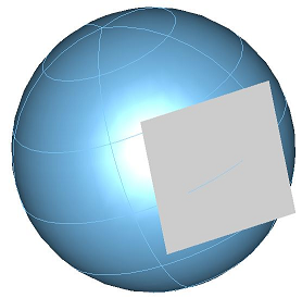
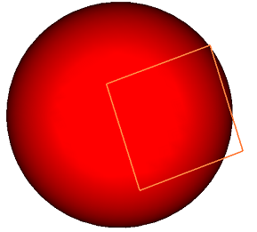
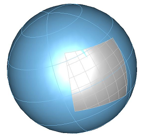
The next steps show the bending of a sheet on a sphere:
|
1. Step: Align the sheet on the sphere |
2. Step: Pick the spherical surface |
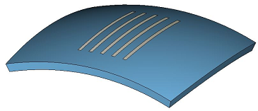
3. Step: Bend the sheet on the sphere |
|
|
|
|
Example: Bend sheet on a solid that consists of a not developable surface
|
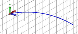
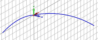
1. Step: Create a spline curve, and align local wcs on an endpoint of the curve and rotate it 90 degree by v-axis |
2. Step: Create a new spline curve by starting in the origin of the local wcs |
3. Step: Sweep first curve along second curve (each curve item has to be in its own curve component) |
|
|
|
|
|
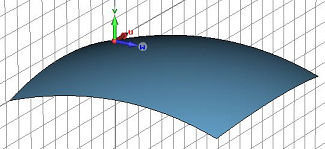
4. Step: By thickening the selected face you get a solid with a doubly-curved surface |
5. Step: To create your sheet(s) which you want to bend, first align local wcs with a point on the face, and then with the face of the solid. |
6. Step: Now bend the sheet(s) on the solid as explained in the firsts example
|
|
|
|
|
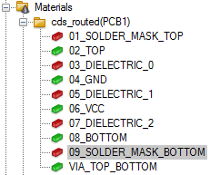
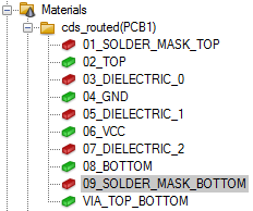
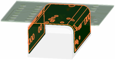
Example: Bend a printed-circuit board (PCB) design with thick layers on a solid
For bending a PCB please note the following:
Layers which have the same bottom coordinate should be bent together.
Vias must be bent together with the bottom or top layer.
Multiple selection of material layers is possible and very useful for the selection.
|
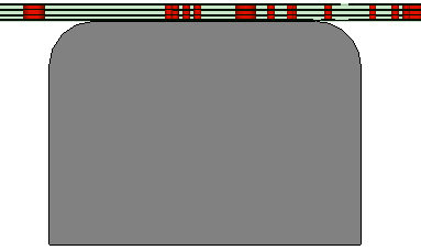
1. Step: Import your PCB data. In the EDA import dialog, for all layers use the setting "above" for the "Filling from" option. |
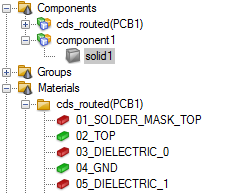
2. Step: Create the solid on which you want to bend the PCB. Position the solid such that one planar face of the solid touches the bottom of the layer stackup. | |
|
|
| |
|
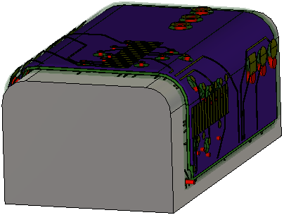
3. Step: Select the layer which is touching the top face of the brick.
|
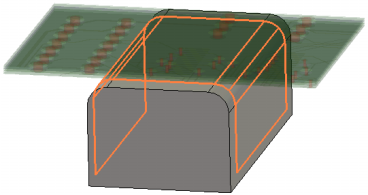
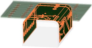
4. Step: Start the bending operation and select the brick by double-clicking in the 3d view. |
5. Step: Select the faces on which you want to bend the PCB layer, and confirm the bending by pressing RETURN. |
|
|
|
|
|
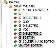
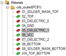
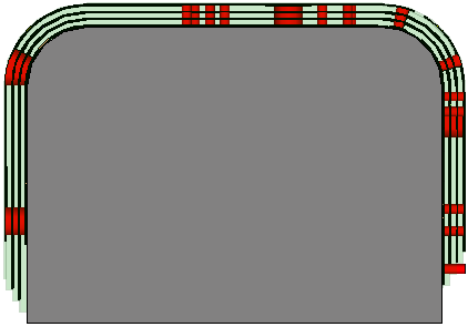
6. Step: Select the next layers
which have the same bottom coordinate and are touching the already bent
solder mask layer. |
7. Step: Select the already bent solder mask layer. |
8. Step: Select the faces on which you want to bend, and confirm the bending by pressing RETURN. |
|
|
|
|
|
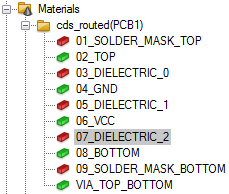
9. Step: Select the next layers
which have the same bottom coordinate and are touching the already bent
dielectric layer. |
10. Step: Select the already bent dielectric layer. |
11. Step: Select the faces on which you want to bend, and confirm the bending by pressing RETURN. |
|
|
|
|
|
12. Step: Now you may continue
in the same way to bend the remaining layers of the PCB. |
||
|
|
| |
See also
Brick, Cylinder, Elliptical Cylinder, Cone, Extrude Profile, Extrude Face, Rotate Profile, Rotate Face, Loft, Coordinate system, Sphere, Torus, Sweep Curve Along Path.


HFSS视频教程 ADS视频教程 CST视频教程 Ansoft Designer 中文教程
|
Copyright © 2006 - 2013 微波EDA网, All Rights Reserved 业务联系:mweda@163.com |
|