Discrete Face Port
 Sources and Loads Sources and Loads  Discrete Port Discrete Port
Beside waveguide ports or plane waves the discrete ports
offer another possibility to feed the calculation domain with power. The
discrete face port is one kind of discrete port. It is supported by the
integral equation solver, the transient solver, as well as the frequency
domain solver with tetrahedral mesh. The discrete face port is replaced
by a Discrete Edge Port
if any other solver is chosen. Two different types of discrete face ports
are available, considering the excitation as a voltage or as an impedance
element which also absorbs some power and enables S-parameter calculation.
Please refer to the Discrete
Port Overview page to find some more detailed information especially
regarding the construction procedure.
Properties frame
Port type:
Select here the type of the discrete face port. Corresponding to
this setting the input parameters in the properties frame will change.
Please note, that the input signal for the port is normalized
differently, depending on the chosen port type.
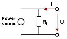
S-Parameter:
This port type is modeled by a lumped element, consisting of a current
source with an inner impedance, which excites and absorbs power. The current
source will only be active, when the discrete element is the stimulation
port in the analysis. This port realizes an input power of 1W and enables
the calculation of correspondent S-parameter. In addition it is also possible
to monitor the voltage across and the current through the discrete face
port. Note that the orientation of the discrete face port is used to determine
the phase of the S-parameters. An equivalent circuit diagram for a discrete
face port of the S-parameter type is shown below.
Voltage:
This port type realizes a voltage source, exciting with a constant voltage
amplitude. In case that this port is not stimulated in the analysis the
voltage along the wire is set to zero. The voltage excitation signal will
be recorded during the solver run.
Current:
This port type realizes a current source, exciting with a constant current
amplitude. The current excitation signal will be recorded during the solver
run.
Name:
Select a valid name from the drop down list. This number will be displayed
next to the discrete face port in structure plots and will be used for
naming the S-parameter results. Please note that the port numbers are
shared with the waveguide port
definitions.
Label:
Here, you may define a label for the port.
Impedance /
Voltage / Current: Specify a numerical
for the input parameter of the discrete face port. Insert either impedance,
voltage amplitude or current amplitude due to the settings made in the
port type frame. In case of the S-parameter selection the resulting S-parameters
will be automatically normed to the specified impedance.
Monitor voltage
and current: If this option is activated,
the voltage across and the current through the discrete face port are
monitored during the simulation. The resulting curves are placed in the
folder 1D Results Discrete Ports Voltages and
1D Results Discrete Ports Currents, respectively.
Please note that the spectral amplitude results
represent peak values and are normalized to the spectrum of the defined
reference signal. In case of the S-parameter discrete port type, all results
refer to an input power of 1 W.
Location frame
If the discrete face port is replaced by a Discrete Port this start
and end point are taken for the Discrete
Port. An extra point can be picked which determines the position of
the discrete edge port if the discrete face port is created by two closed
edge chains.
Excitation
at center edge: The excitation takes place at the center edge of
the port by default or the user picked edges and edge chains respectively.
Invert Direction:
Changes the direction of the discrete face port.
Use projection
on edge: When this check box is activated then one edge is projected
onto the other edge and the discrete face port is created in between the
edge and its projection.
Reverse projection:
Changes the edges used for the projection. That means if the check box
is activated then the second picked edge is projected onto the first picked
edge. This option is only available when Use
projection on edge is active.
OK
Stores the current settings and leaves the dialog
box.
Preview
Press this button to create a preview of the
port. This option is very useful to check the settings before you actually
create the port.
Cancel
Closes this dialog box without performing any
further action.
Help
Shows this help text.
See also
Integral
Equation Solver Overview,
Modeler
View
Discrete
Port Overview, Discrete
Port, Waveguide Port, Reference
Value and Normalization,


HFSS视频教程
ADS视频教程
CST视频教程
Ansoft Designer 中文教程
|
