![]()
![]()
Transient EM/Circuit Co-Simulation
The integration of CST MICROWAVE STUDIO庐 in CST STUDIO SUITE鈩?allows for a straightforward coupling of EM simulation and circuit simulation.
For each CST MICROWAVE STUDIO庐 structure, two fundamentally different views on the model exist. The standard view is the 3D model representation which is visible by default. However, in addition, a schematic view can be activated by selecting the corresponding tab under the main view:

Once this view is activated, the schematic view is shown where the 3D structure is represented by a single block (MWS block) with terminals:
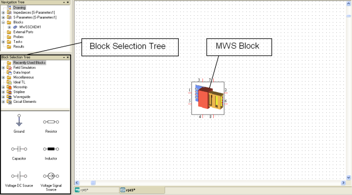
The terminals are a one-to-one correspondence to the 3D structure鈥檚 waveguide or discrete ports. The schematic view now allows for easy addition of external circuit elements to the terminals of the 3D structure.
Adding circuit elements to the schematic view is straightforward. The general procedure is to select a circuit element from the block selection tree and drag it onto the schematic view. The block selection tree is organized into several categories containing elements.
Circuit elements can be accessed through the Circuit Elements folder:
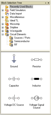
These elements can now either be dragged by pressing the left mouse button on the element itself or even more easily by pressing the left mouse button while the cursor is on one of the element鈥檚 terminals. Note that an element鈥檚 terminal is highlighted by a red circle whenever the mouse pointer is located over it.
Once an element is selected at its terminal and then dragged onto the schematic view, a red dot will appear whenever the terminal is located close to the end of an already existing connection line (here shown for the RJ45 connector example):
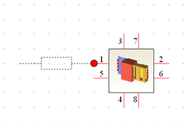
Releasing the mouse button there will then place and connect the circuit element on the schematic. Red terminal lines illustrate that this line is still open-ended whereas blue lines indicate proper connection.
Selecting a circuit element by single-clicking on it will reveal its properties in the parameter window as shown below:
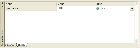
The element鈥檚 properties can be modified in the usual way by clicking into the corresponding entry field and changing the value.
Ground (GND) elements and ports can also be accessed by dragging and dropping them from the block selection tree (for ports select the Circuit Elements冒Sources / Ports section), but convenient shortcuts exist for these frequently used elements:
|
Shortcut |
Description |
|
g |
Place a ground element. Simply click on the end of a connection line after activating this shortcut. |
|
p |
Place a port element. Click on the end of a connection line to place the port |
All elements can be dragged with the mouse to a new location while the elements stay connected via the connection lines. Furthermore, after you select an element, you can rotate it by choosing View冒Tools冒Rotate/Flip Tools冒Rotate Left (shortcut l) and View冒Tools冒Rotate/Flip Tools冒Rotate Right (shortcut r), respectively.
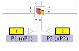
The following picture shows an exemplary external circuit where the original 8-port structure has been reduced to a 2-port device by applying loads to all the other terminals:
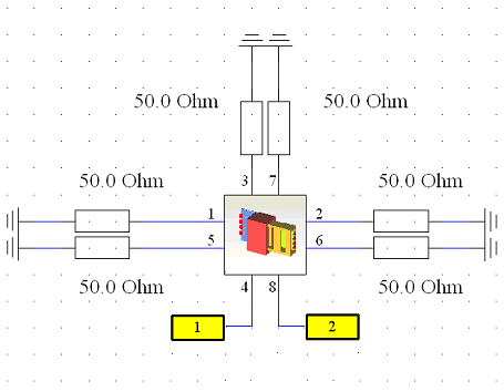
Once all terminals of the MWS block are connected to circuit elements, an S-parameter simulation of the structure including the external circuitry can be performed. The resulting S-matrix will have two ports in the example above, since only two external ports have been placed in the schematic (represented by diamond-like symbols).
In order to run an S-parameter circuit simulation, choose Simulation冒Update. The circuit simulator supports a variety of different analysis options, so you will be prompted to select one of them:

Not all of these options may be available to you due to license restrictions. Here you should select S-Parameters and click OK. A dialog box will appear in which you can specify the settings of the S-parameter calculation:

The most important setting is the Number of frequency steps here. Clicking OK will start the S-parameter simulation of the coupled EM and circuit problem. If all simulation results of the 3D EM simulation are already present, the circuit simulation will only take a few seconds to complete. Otherwise, the missing EM simulation data will be automatically computed first.
Once the simulation is complete, the results will be added to the navigation tree. The Projects folder will contain a list of sub-folders, each of which represent a currently opened project. All data will be stored under the folder for the corresponding project.
The S-parameters will be shown as top-level results of the project folder. Simply clicking on the S-Parameters entry will show the external S-parameters:
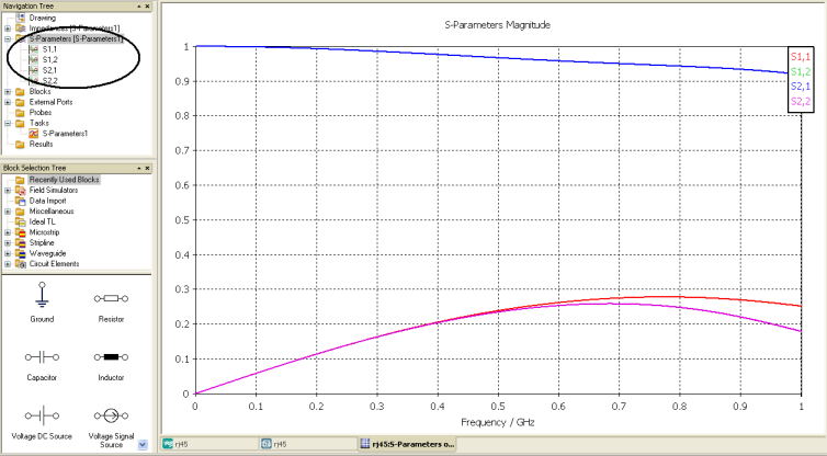
The schematic view also supports the parameterization of the 3D model in a straightforward way by making the structure parameters available as block parameters for the MWS block. This tight coupling of the different simulation methods allows for true EM/circuit co-simulation.
The transient EM/circuit co-simulation is an alternative to the standard EM/circuit co-simulation that is available for coupled circuit-EM problems. The standard EM/circuit co-simulation of CST DESIGN STUDIO鈩?uses S-Parameters to describe CST MICROWAVE STUDIO blocks. The computation of the S-parameters by CST MICROWAVE STUDIO庐 requires either a frequency sweep of the frequency domain solver, or one simulation per port of the time domain solver. The resulting S-parameters describe the block for any combination of port excitations.
The transient EM/circuit co-simulation uses a different approach: Only one simulation of the coupled circuit-EM problem is performed, with exactly the excitation that is defined in the circuit. Both the circuit and the EM problem are solved simultaneously. This approach is usually faster than the standard EM/circuit co-simulation (especially for larger numbers of ports), since no general S-parameters need to be calculated.
The following conditions need to be met for the transient EM/circuit co-simulation:
The circuit must contain exactly one CST MICROWAVE STUDIO schematic block. CST MICROWAVE STUDIO blocks and CST MICROWAVE STUDIO file blocks may also be present, but those will be described by S-parameters as usual and not take advantage of the transient EM/circuit co-simulation.
The CST MICROWAVE STUDIO block must have one or more port. The ports may be of discrete type (edge or face ports) or waveguide type. For waveguide ports only TEM and quasi-TEM modes are allowed. The port type of discrete ports (S-parameter, voltage or current) as well as the port properties (impedance, voltage or current value) are ignored. The discrete port simply defines the location where the circuit voltage and current is fed into the 3D structure.
The circuit must not contain any open pin.
The transient EM/circuit co-simulation is controlled from CST DESIGN STUDIO鈩? In order to perform a transient EM/circuit co-simulation, set up a transient simulation task and select the CST MWS co-simulation option in the task page.
The setup of a transient EM/circuit co-simulation is very similar to the setup of the S-parameter simulation described above. Open the Select Simulation Task dialog box by choosing Simulation冒New Task from the main menu or New Task鈥?from the context menu of the Tasks navigation tree item. Instead of S-Parameters choose Transient as the task type. The following dialog box will appear:

In order to perform a transient EM/circuit co-simulation, select the CST MWS co-simulation radio button in the Circuit simulator frame. Using the Simulation settings frame, set the total simulation time to 5 ns. The number of samples left to 0 (automatic sampling will be used in this case).
Note: The EM/Circuit Co-Simulation makes use of the automatic steady state checking of CST MWS. Whenever the field energy in CST MWS drops below the accuracy level of the CST MWS time domain solver setting, the simulation automatically stops, regardless of the total simulation time Tmax. For periodic time signals this behaviour may not be desired. In this case you need to disable the steady state checking by selecting "No check" in the CST MWS time domain solver setting.
To complete the transient simulation task setup, mark the first port in the Excitation settings frame and press the Signal鈥? button. This will bring up the Excitation Signal dialog box:
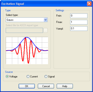
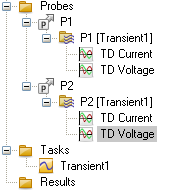
Here you can simply accept the defaults. Now the setup of the transient simulation task is completed, but you have not yet specified which voltages and currents of the circuit you are interested in. This is done by so-called probes: A probe can be attached to any link in your design which will record the associated voltage and current for visualization. To insert a probe, simply drag it from the Miscellaneous folder of the block selection tree onto the desired link. In our simple example we are interested in the voltages and currents at both ports, so we insert two probes:
|
Now the setup of the transient EM/circuit co-simulation is completed, and you may start the simulation with Simulation冒Update. After the simulation has finished, the results appear below the Probes item of the navigation tree. In this simple example you鈥檒l notice the Gaussian pulse fed into port 1 appears at port 2 with a short delay and a bit of attenuation. More realistic examples may of course use any of the excitation signals available from the excitation signal library (including user defined signals). Excitation of more than one port is of course also possible. For further information about transient simulation in general and transient EM/circuit co-simulation in particular, please refer to the online help. |
|
For more information on how to use the schematic view or the many simulation options, refer to the CST DESIGN STUDIO鈩?Getting Started manual.


HFSS视频教程 ADS视频教程 CST视频教程 Ansoft Designer 中文教程
|
Copyright © 2006 - 2013 微波EDA网, All Rights Reserved 业务联系:mweda@163.com |
|