|
|
|
| 首页 >> CST教程 >> CST2013在线帮助系统 |
Changing the Structure's ViewYou may change the view to your structure at any time (even during shape generation) by some simple commands that will be explained in the following section.The view will change whenever you drag the mouse while holding the
left button pressed, depending on the mode selected. The mode may be selected
either from the Ribbon by choosing View:
Mouse Control
|
|
|
|
|
|
|
|
|
|
Zoom |
Pan |
Rotate
|
Dynamic Zoom |
Rotate in Plane |
Reset View |
Reset View to Selection |
Mode
The mode setting effects the behavior as follows:
Zoom: In this mode, a rubber-band rectangle will be defined by dragging the mouse. After releasing the left mouse button, the zoom factor and the view location will be updated so that the rectangle fills the screen.
Pan: The structure will be translated in the screen plane following the mouse cursor movement.
Rotate: The structure will be rotated around the two screen axes.
Dynamic zoom: Moving the mouse upwards will decrease the zoom factor while moving the mouse downwards increases the zoom factor.
The dynamic zoom may also be controlled with the mouse wheel. By default the origin for this operation is located in the center of the screen. Optionally, pressing the CTRL key while using the mouse wheel performs a zoom operation around the current mouse pointer location.
Rotate in Plane: The view plane will be rotated.
The dynamic view adjusting mode is always exited
when the left mouse button is released. You may reset the zoom factor
by choosing View:
Change View![]() Reset
View from the main menu or from the context menus. Alternatively,
you may press the corresponding item in the view Ribbon tab.
Reset
View from the main menu or from the context menus. Alternatively,
you may press the corresponding item in the view Ribbon tab.
One of the most important view-changing commands
is activated by View:
Change View![]() Reset
View to Selection or by pressing SPACE. This command will zoom
the defined structure to a point where it fits well into the drawing window.
If you have selected a part of the structure SHIFT+SPACE will zoom to
the selected object only.
Reset
View to Selection or by pressing SPACE. This command will zoom
the defined structure to a point where it fits well into the drawing window.
If you have selected a part of the structure SHIFT+SPACE will zoom to
the selected object only.
Because changing the view is a frequently used operation that will sometimes be necessary even during the process of the interactive shape creation, some useful shortcut keys exist:
Holding the CTRL key pressed while dragging the mouse with the left button pressed will have the same effect as if the ”rotation” mode were selected. Holding the SHIFT key instead of the CTRL key allows the rotation of the structure around an axis normal to the display screen. Pressing the CTRL and SHIFT keys simultaneously has the same effect as the ”pan” mode.
Views
Predefined Views:
Show the structure from different viewing angles
(View:
Change View![]() Nearest
Axis/Front/Back/Left/Right/Top/Bottom).
Nearest
Axis/Front/Back/Left/Right/Top/Bottom).
User Defined Views:
Select a previously stored
view (View: Change View![]() User-defined Views
User-defined Views![]() Store View).
Store View).
If the view changes the transitions between the
different views will be animated. You may disable this animation with
View:
Options![]() View Options
View Options![]() Specials
Specials![]() Animate view.
Animate view.
Visibility
Hide or show the selected ports or objects.
Axes Scaling
Use the scale axes feature to change the viewing matrix of the model; the model itself will not be changed.
Cutting Plane
Use View:
Sectional View![]() Cutting Plane (
Cutting Plane (![]() ), View:
Sectional View
), View:
Sectional View![]() Cutting Plane
Cutting Plane![]() Cutting Plane Properties (
Cutting Plane Properties (![]() )
and View:
Sectional View
)
and View:
Sectional View![]() Cutting Plane
Cutting Plane![]() Cutting Plane by Partition Line (
Cutting Plane by Partition Line (![]() ) to toggle, modify
and define
a cutting plane.
) to toggle, modify
and define
a cutting plane.
View Options
Use View:
Options![]() View Options to change the View
Options.
View Options to change the View
Options.
The following settings may also be modified by the corresponding item from the Ribbon tab View::
|
|
|
|
|
Axes
|
Wire Frame |
Drawing Plane |
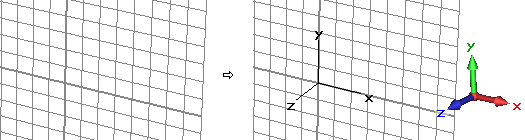
Axes: This option specifies whether the global coordinate system and the fixed axis at the lower right are displayed or not (CTRL+A):
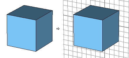
Working plane: With this flag, you may specify whether the drawing plane is visible or not (ALT+W).
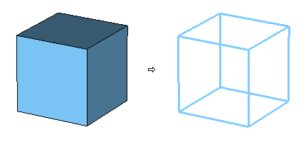
Wireframe: This flag indicates whether all shapes are visualized as simple wire models or as solid shaded objects (CTRL+W).
See also
View Options, Structure Animation, Store View, Axes Scaling


HFSS视频教程 ADS视频教程 CST视频教程 Ansoft Designer 中文教程
|
Copyright © 2006 - 2013 微波EDA网, All Rights Reserved 业务联系:mweda@163.com |
|
