Probe
 Home:
Components
Home:
Components ProbeAdd Probe
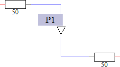
A probe can be associated with a connector to monitor voltages and currents. To add a probe, select the symbol shown above from the block selection tree and drop it at the location of a connector or simply use the shortcut SHIFT+'o' inside the schematic view. A triangle will be added to the connector indicating the current's direction. Furthermore, a name is displayed next to the triangle that is the name of the probe.
The direction of the probe can be changed by selecting the connector that
is associated with the probe in the view and either selecting 'Change
Probe Direction' from the context menu, or selecting Home:Probe![]() Change Direction.
Change Direction.
A corresponding item inside the navigation tree is created as well, where the probe direction can also be changed via the context menu. Results for voltages and currents may be accessed from there.
The voltage of a probe always refers to the circuit’s common ground. A connection to the common circuit ground may be created using the ideal ground block. Voltage differences may be obtained by creating a user defined result plot and selecting two probe voltage curves in the add curve dialog.
See also