Name
Specify a unique name for the wire.
Folder
Choose a folder from the select list. You can also create a new folder by typing the name of the new folder.
Type
The "Type" specifies the shape of the bond wire. There are three options. The first one is "Spline", where a spline curve defines the bond wire. The other two options define the bond wire according to the EIA/JEDEC standard (EIA/JESD59).
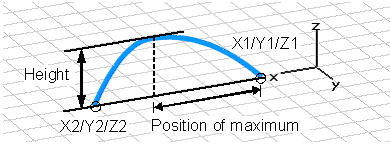
Spline:
|
|
The value "Position of maximum" must be a value between 0 and 1. For a value of 0 the maximum would be above X1/Y1/Z1. For a value of 1 the (maximum would be above X2/Y2/Z2. The example in the picture would have a "Position of maximum" of 4/6.
JEDEC4:
|
|
For this shape only start/end points ("X1/Y1/Z1", "X2/Y2/Z2") and a "Height" need to be specified. All other values are dependent values.
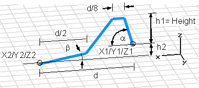
JEDEC5:
|
|
For this shape start/end points ("X1/Y1/Z1", "X2/Y2/Z2"), a "Height" as well as the angles "Alpha" and "Beta" need to be specified. All other values are dependent values.
Radius
Enter the radius of the bond wire here.
Note: If "Solid wire model" is disabled, the radius setting of the bond wire has no effect on the display in the main view.
Height
Specify a valid expression for the height of the wire in normal direction of the working plane (see pictures above).
Position of maximum / Alpha (angle at point1) / Beta (angle at point 2)
Depending on the "Type" you have selected some of these values may be disabled. If they are enabled, you may specify a valid expression for their values. See pictures above for their proper meaning.
U1, V1, W1, U2, V2, W2
Specify a valid expression for the start and end point of the wire in local coordinates. Please note that these entries only appear if a local coordinate system is currently active.
X1, Y1, Z1, X2, Y2, Z2
Specify a valid expression for the start and end point of the wire in global coordinates. Please note that these entries only appear if no local coordinate system is active.
Use Pick
If this option is activated the two recently selected points are used to define the start and end point of the bond wire. Un-check this option to manually change the coordinates.
Solid wire model
This option converts the wire-model into a solid model.
Material
Defines the material of the bond wire. If "Solid wire model" is selected any material can be selected. If "Solid wire model" is not selected only PEC and lossy metal materials can be selected, whereas lossy metal will only be supported by the Integral equation solver.
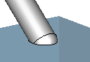
Termination
Only active if "Solid wire model" is selected. Different shapes for the bond wire ends can be chosen:
|
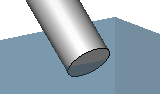
Natural |
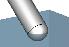
Rounded |
Extended |
|
|
|
|
OK
Press this button to finally create the wire.
Preview
Press this button to create a preview image of the new shape. This option is very useful to check the settings before you actually create the shape.
Cancel
Closes this dialog box without performing any further action.
Help
Shows this help text.
See also
Brick, Sphere, Cylinder, Elliptical Cylinder, Cone, Torus, Extrude Profile, Extrude Face, Rotate, Profile, Rotate Face, Loft, Shell, Coordinate Systems , Pick Points, Edges or Faces Overview, Modeler View