

 2D/EDA Files
 ODB++
ODB++ODB++ databases are organized as a multilevel directory tree on disk. When generating the database, the option of compressing this directory (into ".zip" or ".tgz" archives) should be enabled. The import algorithm un-compresses the directory tree on the fly.
The following PCB design software products support ODB++ output:
Zuken CR-5000 , CADSTAR, Visula
Please check whether your layout software has the ODB++ -generation option installed.
General remark: If you encounter problems creating ODB++ data (e.g. the ODB++ converter of the layout tool reports warnings or errors) please make sure that you have successfully created Artwork data (i.e. Gerber format RS-274D or RS-278X) previously. Then rerun the ODB++ converter.
Remark about multiple steps: Only single-step ODB++ files can be imported, so please delete all but the desired step, as follows: (i) Unzip the ODB++ archive on disk. (ii) In the sub-directory 'matrix', open the file 'matrix' with a text editor. (iii) In the section 'STEP {...', delete the unwanted steps. (iv) pack the whole ODB++ directory structure again by a standard tool, e.g. Linux tar or Windows zip.
Remark about R,L,C component values: Some CAD systems attach component properties to the ODB++ output. These data are extracted into a *.csv spreadsheet (comma-separated file) by the present ODB++ -to-CST import. More...
When generating ODB++ output from within Mentor Graphics® Expedition, the following dialog box appears.
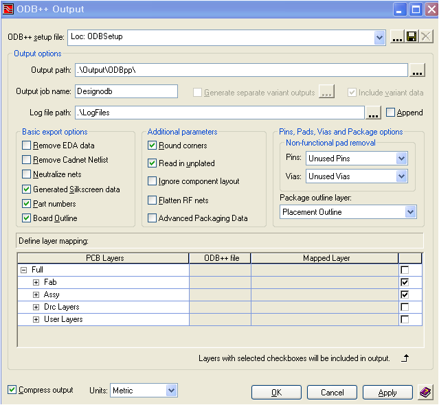
Pressing OK will generate a compressed output (*.zip or *.gz), which can directly be imported into CST STUDIO SUITE. We recommend choosing the above configuration. For details of the ODB++ export options, please consult the Mentor Graphics software documentation.
The Fablink software of the Mentor Graphics® Boardstation
flow supports generation of ODB++. This export extension is included in
the regular Mentor Graphics® Boardstation distribution free of charge.
In Fablink, choose, File Export
 to ODB++..., which opens the following dialog:
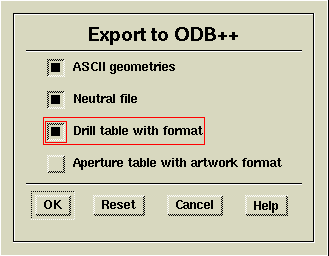
Please check the items ("ASCII geometries", "Neutral file", and "Drill table with format") and click "OK". The following dialog appears:
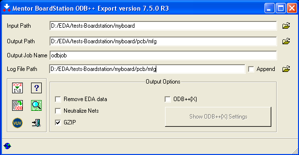
Please check the "GZIP" option. For advanced options, please consult the "Mentor Boardstation ODB++ Export" manual. Pressing "Begin Translation" will create the ODB++ file (here odbjob.tgz on the given "Output Path"). You may move, copy, or rename the created file. Giving the ".tgz" file a name related to the PCB design is recommended (here, e.g. "myboard.tgz"), since the 3D model will carry the same name.
ODB++ data can be generated within the Zuken CR-5000 design flow if the associated software module has been licensed. Please consult the Zuken software documentation for further details. However, using the native CST interface to Zuken CR-5000 is recommended instead of using ODB++.
Please note that for Cadence® Allegro, the usage of the CST-Link is recommended, which offers more flexible selection capabilities.
If working with ODB++ is desired, the free "ODB++ Inside" software package of Mentor Graphics Corporation (http://www.mentor.com) must be installed. In order to create the ODB++ output, take the following steps:
Within the Cadence®
Allegro software, choose File Export
 ODB++ inside.
Answer "No" when asked "Extract net impedance averages?"
In the dialog box appeared, check the "GZIP" option.
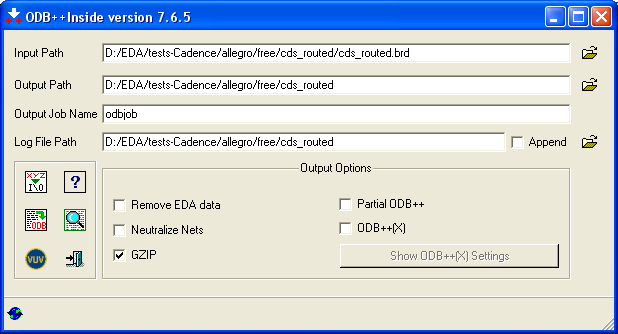
Removal of unconnected/non-functional pads can be switched on in the advanced options ("xyz I/O").
For other advanced options, please consult the "ODB++ inside" manual.
Pressing "Begin Translation" will create the ODB++ file (here odbjob.tgz on the given "Output Path").
You may move, copy, or rename the created file. Giving the ".tgz" file a name related to the PCB design is recommended (here, e.g. "cds_routed.tgz"), since the 3D model will carry the same name.
Altium Designer offers the ability to export ODB++
files directly from the menu bar through 'File
 Fabrication Output
  ODB++ Files'. If this menu item does
not exist yet, please go to 'DXP
  Plug-ins and updates
  Output Generators' , then locate and
install the 'Output - ODB' plug-in.
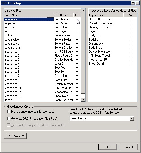
After clicking the menu item, the dialog below pops
up (Altium Designer 10). Please consult the Altium Designer Help for more
information. After pressing 'ok'
in the dialog, the ODB++ file is generated in the same folder as the current
PCB design. Altium will automatically open the built-in CAM-viewer, which
allows the user to review the fabrication output. (It
is not recommended to generate the ODB++ files from within the CAM viewer
(under 'File  Export
  ODB++') as lumped
element information will be lost is this intermediate step.)
Note: If you are experiencing problems with the generated ODB++ files, please verify that you have the latest version of the plugin installed inside Altium Designer.
See also
Importing and Exporting Models