|
微波射频仿真设计 |
|
|
微波射频仿真设计 |
|
| 首页 >> Ansoft Designer >> Ansoft Designer在线帮助文档 |
|
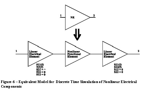
System Simulator > Nonlinear Electrical Component Discrete Time SimulationThe nonlinear discrete time simulation technique described here is used for processing bandpass modulated signals through nonlinear components (e.g., amplifiers, mixers, frequency multipliers). Generally, nonlinear electrical components are not only power dependent, but also frequency and/or temperature dependent. An equivalent model is used for nonlinear components in discrete time simulation to separate the power dependent characteristics from frequency and temperature dependent characteristics. All nonlinear electrical two-port components are assumed unidirectional (i.e., S12 = 0). Each nonlinear electrical component is partitioned into three segments: a linear active input component, a nonlinear functional component followed by an output linear electrical passive and noiseless component. This arrangement is shown in Figure 6 below.
In this model, the power dependent characteristics of S11, S12 and S22 are ignored. The frequency and temperature dependent small signal S11 and NF are associated with the input linear electrical component. The power dependent characteristics of S21 are associated with the nonlinear functional component. The frequency and temperature dependent small signal S21 and S22 are associated with the output linear electrical component. For discrete time simulation, the linear electrical input and output components are associated with other connected linear electrical components and simulated as a linear electrical sub-design as discussed in the previous section. The nonlinear characteristic of a two-port component in Designer is described by its nonlinear figures-of-merit or nonlinear measured data. Only the nonlinear characteristic of S21 is considered in discrete time analysis techniques even though S11, S12 and S22 may possibly be power dependent too.
The topics for this section include: Modeling Nonlinearity using Polynomial Power Series Calculating the Nonlinear Output Voltage
HFSS视频教程 ADS视频教程 CST视频教程 Ansoft Designer 中文教程 |
|
Copyright © 2006 - 2013 微波EDA网, All Rights Reserved 业务联系:mweda@163.com |
|