|
微波射频仿真设计 |
|
|
微波射频仿真设计 |
|
| 首页 >> Ansoft Designer >> Ansoft Designer在线帮助文档 |
|
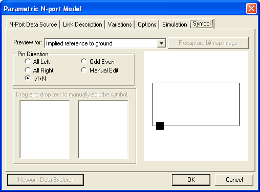
Schematic Editor > Symbol TabThe Symbols tab is used to display symbols for the model:
You can use the following controls to position pins on the symbol: • Preview for: This pulldown menu allows you to choose from the following display options: — Implied reference to ground — Show common reference port — Add individual hidden reference pin per port — Add individual reference pin per port
• Recapture bitmap image: When enabled, this option allows you to restore the original bitmap image of the symbol. • Pin Direction: The pin direction option may be set to one of the following options: — All Left — All Right — I/I+N — Odd-Even — Manual Edit If you choose Manual Edit, use the windows at lower left to Drag and drop text to manually edit the symbol • Network Data Explorer: Allows you to view and manipulate network data by opening the Network Data Explorer. When the N-port Symbol options have been entered, click OK or select another tab.
HFSS视频教程 ADS视频教程 CST视频教程 Ansoft Designer 中文教程 |
|
Copyright © 2006 - 2013 微波EDA网, All Rights Reserved 业务联系:mweda@163.com |
|