|
微波射频仿真设计 |
|
|
微波射频仿真设计 |
|
| 首页 >> Ansoft Designer >> Ansoft Designer在线帮助文档 |
|
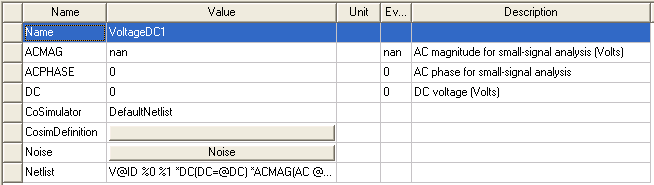
Schematic Editor > Nexxim Port Voltage SourceYou can set up an interface port to be a voltage source for the circuit. In the Add New Source panel, select Voltage and DC, Sinusoidal, Pulsetime, Piecewise Linear, PRBS, or IQ. DC Port Voltage Source In the Add New Source panel, select Voltage and DC. Click Add to selected port. The Properties window displays the parameters for the DC voltage source:
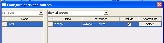
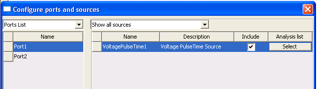
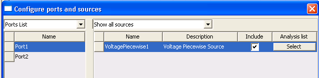
• Assign new values or units to the source parameters in the Parameters window by clicking in the field to be changed. • For Nexxim port voltage sources, you can specify noise data by clicking on the button in the row for the noise property. See Adding Noise Data to a Nexxim Port Source for details. • When all parameters have been entered, click OK. • The Select Analysis dialog opens. Use the checkboxes to associate the source with one or more analyses. • The Configure ports and sources dialog box now shows the new source.
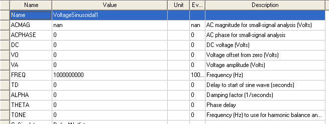
Sinusoidal Port Voltage Source In the Add New Source panel, select Voltage and Sinusoidal. Click Add to selected port. The display below shows the Sinusoidal parameters.
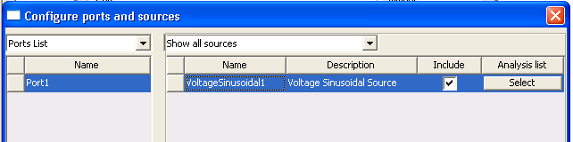
• Click in the Name field to assign a name other than the default. • For Nexxim port voltage sources, you can specify noise data by clicking on the button in the row for the noise property. See Adding Noise Data to a Nexxim Port Source for details. • When all data for the port voltage source have been entered, click OK. • The Select Analysis dialog opens. Use the checkboxes to associate the source with one or more analyses. • The Configure ports and sources dialog box now shows the new source.
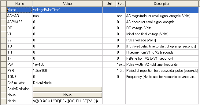
Pulse Port Voltage Source In the Add New Source panel, select Voltage and Pulsetime. Click Add to selected port. Following are the parameters for the Pulse Voltage Source:
• For Nexxim port voltage sources, you can specify noise data by clicking on the button in the row for the noise property. See Adding Noise Data to a Nexxim Port Source for details. • When all data for the port voltage source have been entered, click OK. • The Select Analysis dialog opens. Use the checkboxes to associate the source with one or more analyses. • The Configure ports and sources dialog box now shows the new source.
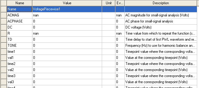
Piecewise Linear Port Voltage Source Following are the parameters for the Piecewise Linear voltage source:
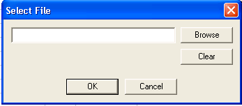
• For Nexxim port voltage sources, you can specify noise data by clicking on the button in the row for the noise property near the bttom of the listing. See Adding Noise Data to a Nexxim Port Source for details. • If the PWL data are in a file, click the PWL_FILE button near the bottom of the property listing. The Select File dialog opens:
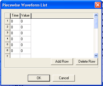
Use the Browse button to locate the file, then click OK to return to the Properties window. • The PWL data file should contain two columns of data: the first for time points and the second for corresponding data points. • A pound sign (#) on the first line indicates a header which is used to set the units of measure for the time and data points. For example, the header “# ns mv” sets the time unit to nanoseconds and the data unit to millivolts. (The header is optional, however, and the default unit values are seconds and volts.) • Comment lines are indicated by an exclamation point (!), asterisk (*), or semi-colon (;) and all data appearing on a comment line is ignored. • Tabs or spaces are used to separate columns of data — commas are NOT allowed. To enter the PWL data manually, click on the PWL_DATA button to open a window for entering the PWL time points and corresponding current values:
When all time points and values have been entered, click OK to return to the Properties window. When all parameters have been entered, click OK. • The Select Analysis dialog opens. Use the checkboxes to associate the source with one or more analyses. • The Configure ports and sources dialog box now shows the new source.
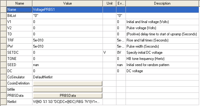
PseudoRandom Bit Source Port Voltage Source In the Add New Source panel, select Voltage and PRBS. Click Add to selected port. The Properties window lists the PRBS source parameters, as in the screen image below.
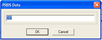
• Click in the Name field to assign a name other than the default (“PowerIQn”). • Assign new values or units to the source parameters in the Parameters window by clicking in the Value or Unit field to be changed. • To assign the PRBS bitlist manually, click the PRBS Data button. The PRBS Data dialog opens:
Use the field in the panel to enter the data. Click OK to return to the Properties window. • If the bitlist data are in a file, click the Bitfile button near the bottom of the property listing. The Select File dialog opens:
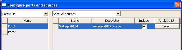
• Use the Browse field to locate the data file. Click OK to return to the Properties window. • When the PRBS data has been specified, click OK to close the Properties window. The Select Analysis dialog opens. Use the checkboxes to associate the source with one or more analyses. Click OK. • The Configure ports and sources dialog box now shows the new source.
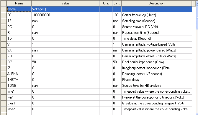
IQ-Modulated Port Voltage Source In the Add New Source panel, select Voltage and IQ. Click Add to selected port. The Properties window lists the IQ source parameters, as in the screen image below.
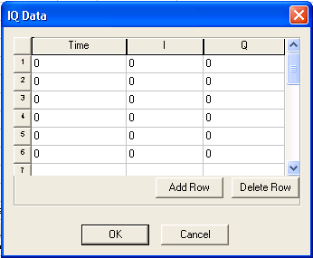
• Click in the Name field to assign a name other than the default (“PowerIQn”). • Assign new values or units to the source parameters in the Parameters window by clicking in the Value or Unit field to be changed. • To assign the IQ time and data point manually, either enter the values in the time, ival, and qval parameter fields, or scroll down to the bottom of the property listing and click theIQ Data button. The IQ Data dialog opens:
Use the fields in the panel to enter the data. New rows are added automatically as you type. You can also add a row (to the end of the list) by clicking Add Row, or delete a selected row by clicking Delete Row. Click OK to return to the Properties window. • If the IQ data are in a file, click the File button near the bottom of the property listing. The Select File dialog opens:
• Use the Browse field to locate the data file. Click OK to return to the Properties window. • When the IQ data has been specified, click OK to close the Properties window.
The Select Analysis dialog opens. Use the checkboxes to associate the source with one or more analyses. Click OK. • The Configure ports and sources dialog box now shows the new source.
HFSS视频教程 ADS视频教程 CST视频教程 Ansoft Designer 中文教程 |
|
Copyright © 2006 - 2013 微波EDA网, All Rights Reserved 业务联系:mweda@163.com |
|