|
微波射频仿真设计 |
|
|
微波射频仿真设计 |
|
| 首页 >> Ansoft Designer >> Ansoft Designer在线帮助文档 |
|
Schematic Editor > Checking ConnectivityThe Electric Rule Check (ERC) feature checks the circuit for valid connectivity. ERC automatically conducts rule checking for ports, connections, and components of the active schematic.
1. To test for connectivity, select Schematic > Electric Rule Check, which opens the following dialog: 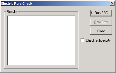 2. Select Check subcircuits to run the electric rule check on subcircuits of the active schematic display 3. Click Run ERC to begin the error check 4. If an error is displayed in the Results window double-click the error message or select the message and click Goto Error to go directly to the object in the Schematic Editor that caused the error. 
Possible causes of Electric Rule Check error messages include: • Unconnected Pins — A component, or port, with a pin that is not connected to anything else. • Overlapping Components — A component that completely overlaps another such that the two components appear as one component. (Often caused by accidentally clicking twice when placing a component.) • Nets with Multiple Output Pins — A net which has more than one output pin connected to it. (This is rare since most component pins are labeled as input and output.)
HFSS视频教程 ADS视频教程 CST视频教程 Ansoft Designer 中文教程 |
|
Copyright © 2006 - 2013 微波EDA网, All Rights Reserved 业务联系:mweda@163.com |
|


