|
微波射频仿真设计 |
|
|
微波射频仿真设计 |
|
| 首页 >> Ansoft Designer >> Ansoft Designer在线帮助文档 |
|
HFSS and Planar EM Simulators > HFSS Model ExtentsThe EM Design type can be simulated directly using HFSS. To achieve this, the bounding computational region (extents) for HFSS must be defined. To access the setup dialog for HFSS Model Extents, select EM Design > HFSS Extents when an EM Design is active. Alternatively, HFSS Extents can be accessed from the Project Manager tree by right-clicking on the EM Design and selecting HFSS Extents. 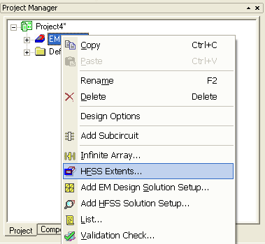
This opens the Set HFSS Model Extents dialog. 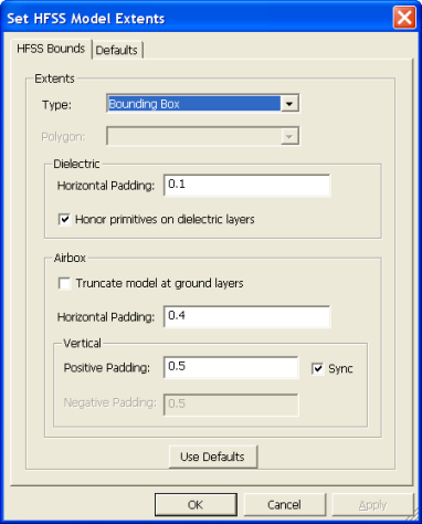
The following controls are available:
Type: Specifies the method used to derive the base-polygon for the extents region. • Bounding Box: The base-polygon is calculated as the bounding box of all active layout geometry across all layers. • Conformal: The base-polygon is calculated as the union of all active layout geometry across all layers. • Polygon: The base-polygon can be selected from all polygons present on user layer types. Polygon: The user polygon to be used.
Dielectric: Defines how the polygon for dielectric and ground layers will be generated relative to the base-polygon. • Horizontal Padding: An expansion factor (unitless fraction) or absolute offset (e.g. 1mm, 20um) to be applied to the base-polygon in constructing HFSS geometry for dielectric layers. • Honor primitives on dielectric layers: If checked and layout geometry is present on a dielectric layer, that geometry will be created for the HFSS simulation. If not checked, the geometry will be ignored and an expanded base-polygon will be created.
Airbox: Defines how the airbox will be generated relative to the base-polygon. • Truncate model at ground layers: If checked and ground layers are present such that regions above or below are electromagnetically isolated from all sources, cap the simulation volume at these elevations. Any horizontal padding on the airbox will be ignored. • Horizontal Padding: An expansion factor or absolute offset to be applied to the dielectric-polygon in constructing the HFSS geometry for the airbox. • Vertical: Expansion factors for the Z-dimension. — Positive Padding: Expansion factor or absolute offset for the +Z dimension of the airbox. When applying as an expansion factor, the base dimension is the maximum of either length or width of the dielectric-polygon. — Negative Padding: Expansion factor or absolute offset for the -Z dimension of the airbox. — Sync: Synchronize Positive and Negative Padding settings. Use Defaults: Populate the Extents settings from the user's saved defaults.
Click the Defaults tab to display the following. 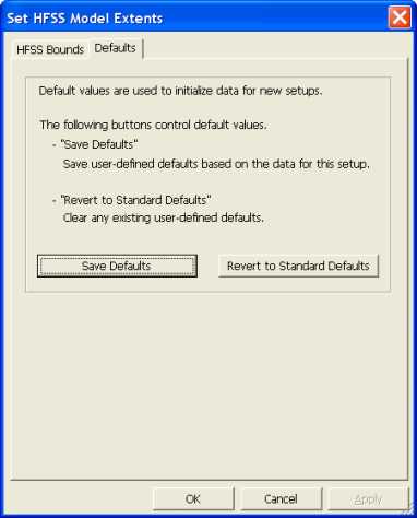 Use the Defaults tab of the Set HFSS Model Extents dialog to: • Save Defaults: Save user-defined defaults based on the data for this setup (for all tabs). • Revert to Standard Defaults: Clear any existing user-defined defaults (for all tabs).
HFSS视频教程 ADS视频教程 CST视频教程 Ansoft Designer 中文教程 |
|
Copyright © 2006 - 2013 微波EDA网, All Rights Reserved 业务联系:mweda@163.com |
|


