|
微波射频仿真设计 |
|
|
微波射频仿真设计 |
|
| 首页 >> Ansoft Designer >> Ansoft Designer在线帮助文档 |
|
Nexxim Simulator > Voltage Source, IQ Modulated
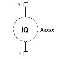 IQ Modulated Voltage Source Netlist FormThe netlist format for an IQ modulated voltage signal generator is: Axxxx n+ n- [DC=val]
[TIMES=[t1 ...tN] I_T=[iv1 ... ivN] n+ and n- are the positive and negative nodes. The brackets shown in bold are required. The parameter FILE =file_reference refers to an external file containing the IQ data. See File References in the Nexxim Netlist File Format topic for details.
The entry COMPONENT=vsiq_source is required.
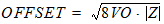
IQ Voltage Source Netlist ExampleAiqtest 23 53 FILE='C:/iqdatadirectory/iqdata.txt’ FC=2.5e9 COMPONENT=vsiq_source Notes1. If lists of times and values are present, the time points t1 ... tN must be given in STRICTLY INCREASING order. Two points may not refer to the same time. 2. If a FILE is referenced, any time and data points in the instance statement will be ignored. 3. The IQ modulated signal generator can be used as a source of data for Nexxim envelope analysis. See Envelope Analysis for details. 4. The IQ modulated signal generator implements the following generalized formula: Output(t) = [Idata(t + TD) + DC] Where parameter FC specifies the carrier frequency, parameter TD specifies the time delay, parameter THETA specifies the phase delay, and AC is the carrier amplitude, calculated as follows: • When parameter V is specified, carrier amplitude is voltage-based. Voltage-based carrier amplitude AC = V and carrier amplitude OFFSET = VO in volts. • When parameter VA is specified and parameter V is not specified, carrier amplitude is power-based. Carrier amplitude AC and carrier amplitude OFFSET are both in watts and use the formulas:
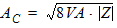
and
Where:
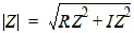
5. The carrier value is specified either with voltage using parameters V and VO or with power using parameters VA, VO, RZ, and IZ. If neither V nor VA is present in the statement, carrier amplitude and offset are assumed to be voltage-based, and the default value of V (1.0 volt) is used. If both V and VA are present in the statement, an error occurs and simulation halts. 6. When parameter ALPHA is non-zero, the
output is attenuated by a factor of 7. The IQ data file can have one of two formats. The first format supplies the timepoints and the corresponding I data and Q data points, with one ordered triple (t1 iv1 qv1) per line. Here is an example: 0.000000e+000 6.931656e-002 5.214852e-004 1.562500e-008 8.616453e-002 7.359377e-004 3.125000e-008 9.932127e-002 3.344250e-004 4.687500e-008 1.080741e-001 -7.217573e-004 6.250000e-008 1.122943e-001 -2.077420e-003 7.812500e-008 1.122116e-001 -3.040601e-003 9.375000e-008 1.083193e-001 -2.843184e-003 1.093750e-007 1.015003e-001 -1.031725e-003 1.250000e-007 9.329680e-002 2.164318e-003 1.406250e-007 8.610437e-002 5.661823e-003 1.562500e-007 8.304946e-002 7.670866e-003
The second format omits the timepoints. Each line contains the two data points (iv1 qv1): 6.931656e-002 5.214852e-004 9.932127e-002 3.344250e-004 1.080741e-001 -7.217573e-004 1.122943e-001 -2.077420e-003 1.122116e-001 -3.040601e-003 1.083193e-001 -2.843184e-003 1.015003e-001 -1.031725e-003 8.610437e-002 5.661823e-003 8.304946e-002 7.670866e-003 When the second format is used, the instance line must specify a value for the sampling time, TS. The data points will be assumed to start at time 0, and each successive pair of points will be simulated at times that differ by the sampling time. When the data file contains time points, the TS entry, if present in the instance statement, will be ignored. 8. The time delay specified by TD=delay is applied to the start of the IQ waveform, so that the wave starts at (time1 + delay). 9. The repeat specified by R=repeattime repeats the portion of the IQ waveform that lies between repeattime and timeN. The repeattime must be greater than or equal to 0.0 seconds, and less than timeN. The repeat begins at tN, subject to any delay. The delay is applied to the repeattime as well as to the PWL waveform, so that the repeating segment is the portion of the PWL waveform between (repeattime + delay) and (timeN + delay). The repeating wave starts at the PWL value that occurred at repeattime in the original wave, interpolated if necessary. 10. For harmonic balance analysis, the test tones must be submultiples or equal to the frequencies of the actual voltage or current inputs to the circuit. To ensure that the desired HB frequency is used with a VSIQ source, qualify the source by adding a TONE=tone_val entry at the end of the instance statement. The tone_val is then used in a subsequent HB statement.
HFSS视频教程 ADS视频教程 CST视频教程 Ansoft Designer 中文教程 |
|
Copyright © 2006 - 2013 微波EDA网, All Rights Reserved 业务联系:mweda@163.com |
|


