|
微波射频仿真设计 |
|
|
微波射频仿真设计 |
|
| 首页 >> Ansoft Designer >> Ansoft Designer在线帮助文档 |
|
Nexxim Simulator > Voltage Source, Sinusoidal
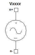 Sinusoidal Voltage Source Netlist FormThe format for a damped sinusoidal voltage source is: Vxxxx n+ n- [DC=val]
SIN ( vo va [freq [td [alpha
[theta]]]] ) n+ and n- are the positive and negative nodes. The parameters after the SIN keyword must be enclosed in parentheses. These six parameters are positional, and must be entered in the order given. To guarantee that a given parameter is interpreted correctly, all parameters to the left of it must be present.
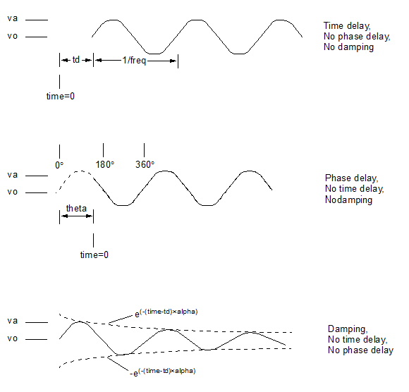
Sinusoidal Voltage Source Netlist ExampleV23 15 21 DC=3 SIN (0 1 100e+3 1e-12 1e-4 20) Notes1. The AC parameter specifies the AC magnitude and phase to be applied during a small-signal AC analysis. The default for acmag is 1 Volt, the default for acphase is 0 degrees. 2. The vo parameter overrides the DC parameter in all analyses except DC analysis. 3. The diagrams below show sinusoidal outputs with time delay, phase delay, and damping.
4. For harmonic balance (HB) analysis, the test tones must be submultiples or equal to the frequencies of the actual voltage or current inputs to the circuit. To ensure that the desired HB frequency is used with a SIN, PWL, or PULSE source, qualify the source by adding a TONE=tone_val parameter at the end of the instance statement. The tone_val is then used in a subsequent HB statement. 5. The TONE parameter is needed with a SIN voltage or current source only when the driving frequency of the source differs from the frequency at which the harmonic balance is to run. For example, to analyze a circuit driven by a single 1-KHz AC voltage source using harmonic balance at a test tone of 1 KHz over the first 31 harmonics, the netlist would be simply: V1 1 0 SIN(0 5.0 1000 0 0) .HB TONES=1000 MAXK=31 However, to specify a 1000-Hz tone for harmonic balance while driving the circuit with a 2000-Hz sinusoidal voltage, the voltage source statement should include the TONE specification: V1 1 0 SIN(0 5.0 2000 0 0) TONE=1000 .HB TONES=1000 MAXK=31
HFSS视频教程 ADS视频教程 CST视频教程 Ansoft Designer 中文教程 |
|
Copyright © 2006 - 2013 微波EDA网, All Rights Reserved 业务联系:mweda@163.com |
|