|
微波射频仿真设计 |
|
|
微波射频仿真设计 |
|
| 首页 >> Ansoft Designer >> Ansoft Designer在线帮助文档 |
|
Nexxim Simulator > Voltage Source, Piecewise Linear
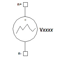 Piecewise Linear Voltage Source Netlist FormThe netlist format for a piecewise linear voltage source is: Vxxxx n+ n- [DC=val]
PWL (t1 v1 [t2 v2... tN vN] n+ and n- are the positive and negative nodes. The parentheses around the parameters after the PWL keyword are required. The first time-value pair (t1 v1) is required, while subsequent pairs are optional.
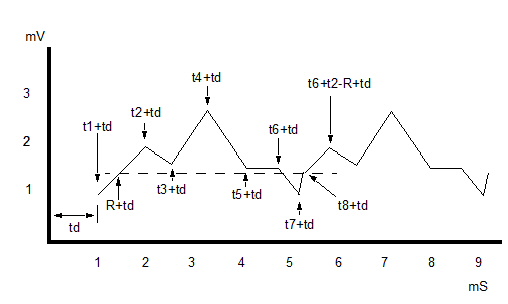
Piecewise Linear Voltage Source Netlist ExampleVpwl 23 53 PWL (0 0 10ns 0.5 15ns 1.5 20ns 0 R TD=3e-12) Notes1. The time points t1 ... tN must be given in STRICTLY INCREASING order. Two points may not refer to the same time. 2. The time delay specified by TD=delay is applied to the start of the PWL waveform, so that the wave starts at (time1 + delay). 3. The repeat specified by R=repeattime repeats the portion of the PWL waveform that lies between repeattime and timeN. The repeattime must be greater than or equal to 0.0 seconds, and less than timeN. The repeat begins at tN, subject to any delay. The delay is applied to the repeattime as well as to the PWL waveform, so that the repeating segment is the portion of the PWL waveform between (repeattime + delay) and (timeN + delay). The repeating wave starts at the PWL value that occurred at repeattime in the original wave, interpolated if necessary. 4. The transition from the PWL value vN at time tN to the (possibly interpolated) value at the start of the repeat can create a discontinuity in the output, especially if the transition is “instantaneous,” that is, occurring with no time difference between the two values. Care should be taken to avoid such a discontinuity, or to ensure that it is very small if it cannot be avoided. Discontinuous current or voltage jumps larger than a minimum value can create a timestep problem for transient analysis. 5. Here is an example using eight time points plus a time delay, with a repeat time (R) that occurs between timepoints, so that interpolation is required. V2 1 0 PWL( + 0.0 1.0e-3 $ t1 v1 + 1.0e-3 2.0e-3 $ t2 v2 + 2.6e-3 1.6e-3 $ t3 v3 + 3.3e-3 2.7e-3 $ t4 v4 + 4.1e-3 1.6e-3 $ t5 v5 + 4.7e-3 1.6e-3 $ t6 v6 + 5.2e-3 1.0e-3 $ t7 v7 + 5.3e-3 0.4e-3 $ t8 v8 + ) R=0.4e-3 TD=1.0e-3 Note the use of timepoint t8 to avoid an “instantaneous” jump in output where the repeat begins. If t8 were omitted, the output would change from the level at t7 to the (interpolated) value at the start of the repeat with no time difference between the two values. Such a sudden discontinuity can cause a timestep-too-small failure in transient analysis. The diagram below illustrates this example, showing one repeat:
6. The AC parameter specifies the AC magnitude and phase to be applied during a small-signal AC analysis. The default for acmag is 1 Volt, the default for acphase is 0 degrees. 7. For harmonic balance analysis, the test tones must be submultiples or equal to the frequencies of the actual voltage or current inputs to the circuit. To ensure that the desired HB frequency is used with a SIN, PWL, or PULSE source, qualify the source by adding a TONE=tone_val entry at the end of the instance statement. The tone_val is then used in a subsequent HB statement. 8. The TONE entry is required with any PWL or PULSE source. For example, to analyze a mixer driven by sources at 1 MHz and 27 kHz over the first four harmonics of a PWL source and the first two harmonics of a PULSE source, the netlist syntax would be: V23 20 0 PWL(0 0 0.1e-6 2.0 0.5e-6 5.0 1.0e-6 0 R) TONE=1.0e6 V1 1 0 PULSE (0 5 0 5e-3 5e-3 27e-3 27.0e3) TONE=27.0e3 .HB TONES=(1.0e+6, 27.0e+3) MAXK=(4, 2) 9. The parameter PWL_FILE =file_reference refers to an external file containing the PWL data. See File References in the Nexxim Netlist File Format topic for details. The format of the PWL data file is: t1 v1 [t2 v2 ...]
HFSS视频教程 ADS视频教程 CST视频教程 Ansoft Designer 中文教程 |
|
Copyright © 2006 - 2013 微波EDA网, All Rights Reserved 业务联系:mweda@163.com |
|