淘宝官方店     推荐课程     在线工具     联系方式     关于我们  


微波射频仿真设计   Ansoft Designer 中文培训教程   |   HFSS视频培训教程套装


Agilent ADS 视频培训教程   |   CST微波工作室视频教程   |   AWR Microwave Office

          首页 >> Ansoft Designer >> Ansoft Designer在线帮助文档


Ansoft Designer / Ansys Designer 在线帮助文档:


Nexxim Simulator >
Nexxim Component Models >
Independent Sources >
   Voltage Source, CPM Modulated       

Voltage Source, CPM Modulated


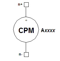
CPM Modulated Voltage Source Netlist Form

The netlist format for a Continuous-Phase Modulation (CPM) voltage signal generator is:

Axxxx n+ n- [M=val] [FB=val]
SEED=val [BITLIST=#bitlist] [BITFILE=file_reference]
[UPCHOICE=val] [UPFACTOR=val]
[V=val] [VO=val]
[FREQ_DEVIATION=val]
[ALPHA=val] [THETA=val] [TONE=val]
[FILTCHOICE=val] [NTAPS=val]
[ROLLOFF=val] [NORMALIZESCHEME=val] [BT=val]
[FC=val] [TD=val]
[NOISEVEC=[f1,psd1, ... fn,psdn]]
COMPONENT=cpm_iq_source

n+ and n- are the positive and negative nodes. The brackets shown in bold are required.

The entry COMPONENT=cpm_iq_source is required.

The CPM modulated signal generator can be used as a source of data for Nexxim envelope analysis. See Envelope Analysis for details.


CP-Modulated Voltage Source Parameters

Parameter

Description

Unit

Default

M

Modulation level (2=binary, 4=quaternary)

None

4

SEED

Integer seed for random pattern [Must be greater than 0.0]

None

None

BITFILE

Reference to external file with the bit values

None

None

BITLIST

Explicit list of bits to generate

None

None

FB

Data rate

Bits/Second

1.2288e6

FREQ_DEVIATION

Frequency deviation

Hertz

307.2e3

ALPHA

Damping factor

Second-1

0.0

THETA

Phase delay

Degree

0.0

TD

Time delay to start of first waveform, and to start of first repeat

Second

0.0

V

Output voltage

Volt

None

VO

Voltage offset

Volt

0.0

UPCHOICE

Upsampling technique.

1 = Zero insertion

0 = Sample repeat

None

1

UPFACTOR

Upsampling factor

None

10

TONE

Frequency to use for harmonic balance analysis. Should be the same as FC.

Hertz

0.0

FC

Carrier frequency

Hertz

1e9

FILTCHOICE

Low pass filter selector

1 = No filter

2 = Spectral raised cosine (SRC)

3 = Square root spectral raised cosine (SRRC)

4 = Rectangular (REC)

5 = Gaussian GAUSS)

None

1

NTAPS

Number of filter taps

None

31

NORMALIZESCHEME

Normalization method for tap coefficients (weights)

1 = No normalization

2 = Maximum sum (amplitude) of coefficients is 1

3 = L1 norm of coefficients is 1

4 = L2 norm of coefficients is 1

None

1

ROLLOFF

Controls the excess bandwidth parameter for SRC and SRRC filters (0< ROLLOFF <1)

None

0.35

BT

Bandwidth-time product, for FILTCHOICE=5 (GAUSS)

None

0.25

NOISEVEC

List of shot noise frequencies (f1...fn) and corresponding noise power spectral densities (psd1...psdn), in pairs.

The sequence of frequencies must be monotonically non-decreasing.

Hertz,
Volt2/Hertz

None


CPM-Modulated Voltage Source Netlist Example

Notes

When no BITLIST or BITFILE argument is supplied, the CPM voltage source generates a pseudorandom bit sequence, starting from a random seed value. When no BITLIST or BITFILE is present, the optional SEED can be used to control the bit sequence. The SEED must be an integer value (the maximum absolute value is the maximum size of integers on your system). Using the same SEED guarantees that the same sequence of bits will be generated on each simulation.

When a BITLIST or BITFILE is supplied, the CPM source generates the specified sequence of 0 and 1 bits, and repeats the sequence until simulation terminates. When a BITLIST or BITFILE is present, any SEED value will be ignored. If two or all three of BITFILE, BITLIST, and SEED are present, Nexxim uses the precedence order: BITFILE > BITLIST > SEED.

In all cases, the sequence of generated bits starts after the time delay given by TD, and continues until the stop time (tstop) of the transient analysis is reached.

The parameter BITFILE =file_reference refers to an xternal file containing the data. See File References in the Nexxim Netlist File Format topic for details.

For harmonic balance analysis, the test tones must be submultiples or equal to the frequencies of the actual voltage or current inputs to the circuit. To ensure that the desired HB frequency is used with a VCPM source, qualify the source by adding a TONE=tone_val entry at the end of the instance statement. The tone_val is then used in a subsequent HB statement.


HFSS视频教学培训教程 ADS2011视频培训教程 CST微波工作室教程 Ansoft Designer 教程

                HFSS视频教程                                      ADS视频教程                               CST视频教程                           Ansoft Designer 中文教程


      Copyright © 2006 - 2013   微波EDA网, All Rights Reserved    业务联系:mweda@163.com