|
微波射频仿真设计 |
|
|
微波射频仿真设计 |
|
| 首页 >> Ansoft Designer >> Ansoft Designer在线帮助文档 |
|
Nexxim Simulator > Voltage Source, AM (Netlist Only)
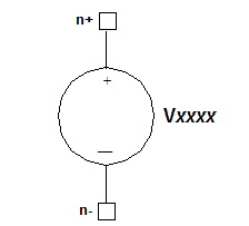 AM Voltage Source Netlist FormatThe netlist format for amplitude-modulated, time-varying (AM) voltage source is: Vxxxx n+ n- AM (sa oc fm fc [td]) n+ is the positive node and n- is the negative node of the voltage source. Parameters in parentheses are positional. The first four parameters must be present in the order given.
AM Voltage Source Netlist Example* AM Voltage Source netlist example * V1 1 0 AM (80 0 5e6 1e9 0) V1 1 0 AM (20 4 5e6 1e9 0) R1 1 0 1 .TRAN 1e-10 1e-6 .PRINT tran V(1) .END Notes1. The AM voltage source output is calculated as follows:
HFSS视频教程 ADS视频教程 CST视频教程 Ansoft Designer 中文教程 |
|
Copyright © 2006 - 2013 微波EDA网, All Rights Reserved 业务联系:mweda@163.com |
|


