|
微波射频仿真设计 |
|
|
微波射频仿真设计 |
|
| 首页 >> Ansoft Designer >> Ansoft Designer在线帮助文档 |
|
Nexxim Simulator > S-Element
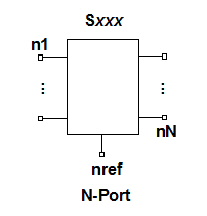 S-Element Instance Netlist FormatThe S-element is an N-port (N+1 terminal) element characterized by a set of frequency-dependent scattering (S) parameters. Refer to Placing N-Ports in the Schematic Editor documentation for details on the use of the N-port element. The Nexxim netlist parser recognizes several netlist formats for the S-element, to allow for variations in models and in reference nodes.
S Model or SP Model, Common Reference NodeThe first format references either an S-model or an SP-model, using a common reference for all ports: Sxxx n1 ... nN nref FQMODEL=modelname [Zo=val[, val ...]] [M=val] [PASSIVE=val] [NOISEMODEL=external|internal|none] [unused_nodes=[(node, val), ...]] [DELAYHANDLE=0|1] [LOWPASS=0|1|2|10|14|15|16] n1 through nN are the N signal nodes. nref is the voltage reference node common to all signal nodes. FQMODEL Parameter FQMODEL indicates that modelname is the name of an SP or S model defined elsewhere in the netlist. The SP model specifies the frequency-dependent data (see SP Model). The S model references frequency-dependent data from a file in the TouchstoneÒ format (TouchstoneÒ is a registered trademark of Agilent Corporation.) See S Model. The FQMODEL format is the one used by Designer for netlists generated from schematics. Zo Parameter Zo is a list of reference impedances for the ports in the device. When only one value is supplied, it is used as the frequency-independent reference impedance for all ports. Multiple values are applied to the ports in the order of the listing. The default for Zo is 50 ohms. M Parameter M is a device multiplier, in effect creating multiple, parallel N-ports with identical node connections. The default for parameter M is 1. PASSIVE Parameter PASSIVE controls passivity checking and enforcement. By default, the input S-parameter data is checked for passivity by doing a singular value decomposition at each frequency point. If any of the singular values are greater than unity, the worst violation is reported in a warning message, along with the frequency at which it occurs. • When PASSIVE=1 has been set, the passivity violations are reported in terms of the minimum eigenvalue of I - S' * S, and violations larger than 0.01% will cause an error message. • When PASSIVE=2 has been set, the passivity of the state-space fit to the data is checked, and if there are any violations of passivity, the worst errors are reported. NOISEMODEL Parameter NOISEMODEL controls noise calculations for DC Analysis and for frequency-domain analyses such as Harmonic Balance. Time-domain analyses do not use NOISEMODEL. • With the default setting, NOISEMODEL=external, Nexxim uses external noise data from the Touchstone file or dynamic link object when it is available. If no external noise data is available, Nexxim uses the internal noise model described in Noise in S-Parameter Elements. • With the setting NOISEMODEL=internal, Nexxim uses the internal noise model described in Noise in S-Parameter Elements. External data is ignored. • With the setting NOISEMODEL=none, no noise calculation is done. External data is ignored. The S-Element option NOISEMODEL sets the noise model for all S-Element instances. The NOISEMODEL parameter on an S-Element instance overrides the global option. Unused_nodes Parameter The parameter unused_nodes enables port reduction, excluding unconnected device ports from the calculations. Brackets open and close the list of unconnected ports. Each entry in the list is a parenthesized pair, (node, val). The node item is the name of the unconnected port or terminal on the component symbol, and the val item specifies the resistance to ground, using the following conventions: • 0 = Connect directly to ground. • -1 = Leave open (connect to infinite resistance) • Any other value = Resistance to ground in ohms The port reduction algorithm takes into consideration any termination for unconnected ports specified on the Terminals tab when the component is edited. See Terminals Tab for details. The unused_nodes parameter enables port reduction only for unconnected ports. The related s_element.reduce option eliminates any ports on the component that are connected directly to ground in the netlist, saving additional compute time. See S-Element Options. DELAYHANDLE Parameter DELAYHANDLE controls the processing of delays when the Convolution method is being used. By default, DELAYHANDLE=0 or OFF, so S-elements do not process delays from incoming sources. When the convolution=1 method is used to process S-parameter data, delay handling can be enabled (the HSPICE S-model parameter DELAYHANDLE=1 or ON is the same as convolution=1). Setting DELAYHANDLE=1 on an S-element conditions that S-element to process delays. LOWPASS Parameter LOWPASS controls the extrapolation method for low-frequency data points that are not supplied in the Touchstone file.
The default for LOWPASS is 16. With this setting, the default for transient analysis is LOWPASS=15, the default for Linear Network Analysis (LNA) or Harmonic Balance is LOWPASS=10. With LOWPASS=0, 1, 2, or 10, interpolation extends down to and including 0 Hz. With LOWPASS=14 or 15, Nexxim calculates the S-parameters at negative frequencies and uses interpolation to estimate the missing data points. Low-frequency S-parameters estimated by spline interpolation (LOWPASS=14) are noncausal, potentially yielding inaccurate results. S Model, Common Reference NodeA second syntax references an S-model (Touchstone file model), using a common reference node for all the ports: Sxxx n1 ... nN nref MNAME=Smodelname [M=val] [PASSIVE=val] [unused_nodes=[(node, val), ...]] n1 through nN are the N signal nodes or ports. nref is the voltage reference node common to all signal nodes. With the keyword MNAME, the Smodelname is the name of an S model defined elsewhere in the netlist. M is a device multiplier, PASSIVE controls the reporting of passivity violations, and unused_nodes controls port reduction, as discussed above. S Model, Ground ReferenceA third format references an S-model (Touchstone file model), using system ground as a voltage reference for all ports: Sxxx n1 ... nN MNAME=modelname [Zo=val[, val ...]] [M=val] [PASSIVE=val] [unused_nodes=[(node, val), ...]] n1 through nN are the N signal nodes. Node zero (system ground) becomes the voltage reference node common to all signal nodes. Node zero is understood, and is not shown in the syntax. With the keyword MNAME, the Smodelname is the name of an S model defined elsewhere in the netlist. The S model references frequency-dependent data from a file in the TouchstoneÒ format (TouchstoneÒ is a registered trademark of Agilent Corporation.) See S Model. Zo is a list of reference impedances for the ports in the device. When only one value is supplied, it is used as the frequency-independent reference impedance for all ports. Multiple values are applied to the ports in the order of the listing. The default for Zo is 50 ohms. M is a device multiplier, PASSIVE controls the reporting of passivity violations, and unused_nodes controls port reduction, as discussed above. S Model, Multiple ReferencesA fourth syntax references an S-model (Touchstone file model) using multiple reference nodes, one for each port: Sxxx n1 ref1 n2 ref2 [ ... nN refN] MNAME=Smodelname [M=val] [PASSIVE=val] [unused_nodes=[(node, val), ...]] n1 through nN are the N signal nodes or ports. ref1 through refN are the N voltage reference nodes, one reference node for each signal node. With the keyword MNAME, the Smodelname is the name of an S model defined elsewhere in the netlist. The S-model in turn references a Touchstone file that specifies the number of ports. ( See S Model.) With this syntax, the total number of nodes must be twice the number of ports (that is, it must specify a separate reference node for each port). M is a device multiplier, PASSIVE controls the reporting of passivity violations, and unused_nodes controls port reduction, as discussed above.
S-Element Instance Netlist ExamplesS1 1 0 FQMODEL=SP_1port Zo=50 S2 4 5 0 MNAME=S_2port
HFSS视频教程 ADS视频教程 CST视频教程 Ansoft Designer 中文教程 |
|
Copyright © 2006 - 2013 微波EDA网, All Rights Reserved 业务联系:mweda@163.com |
|


