|
微波射频仿真设计 |
|
|
微波射频仿真设计 |
|
| 首页 >> Ansoft Designer >> Ansoft Designer在线帮助文档 |
|
Nexxim Simulator > Resistor Device
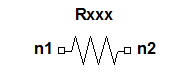 Resistor Device Instance Netlist SyntaxThe general form for a resistor instance is: Rxxxx n1 n2 [modelname] [[R=]val] [[TC1=]val] [[TC2=]val] [M=val] [DTEMP=val] [SCALE=val] [L=val] [W=val] [C=val] [NOISE=val] n1 is the positive node and n2 is the negative node of the resistor. The current is assumed to flow from n1 through the resistor to n2. If a model statement is provided for the resistor, the modelname is its name.
Notes1. In the syntax above, both modelname and the resistance value are shown as optional, but at least one of the two must be supplied. The modelname is identified by matching it to the .MODEL statements in the netlist. The label R= is optional, but the presence or absence of the R= label affects the interpretation of other unlabeled entries in the statement. The first unlabeled value after a modelname is taken to be the resistance value. 2. The syntax above shows the labels TC1= and TC2= as optional, but this option depends on the presence or absence of the resistance value, labeled or unlabeled. • When the modelname is present without a resistance value, the label TC1= or TC2= must be used. • When both modelname and the resistance value are present but the resistance value does not have the R= label, the next two unlabeled values are taken to be TC1, then TC2. To specify a value for TC2, either a value for TC1 must be given as well, or the label TC2= must be used. • When the resistance value is present with the R= label, the labels TC1= and TC2= are required. 3. Minimum Resistance Values The minimum positive or negative resistance value is determined by the global option RESMIN. The default value for RESMIN is 1e-5 Ohm. The value can be changed only in a netlist design. Schematic designs always use the default value. RESMIN always has a positive value. • When a resistor has been given a positive resistance less than RESMIN, a warning is given and the resistance is set to RESMIN. • When a resistor has been given a negative value whose absolute magnitude is less than RESMIN, a warning is given and the resistance is set to -RESMIN. • When a resistor has been given a zero value, a warning is given. If the DEVICE_CLEANUP option has been set, the zero-valued resistor will be replaced with a short circuit. Otherwise, the resistance is set to RESMIN. See Global Device Options for more information on the global options.
HFSS视频教程 ADS视频教程 CST视频教程 Ansoft Designer 中文教程 |
|
Copyright © 2006 - 2013 微波EDA网, All Rights Reserved 业务联系:mweda@163.com |
|


