|
微波射频仿真设计 |
|
|
微波射频仿真设计 |
|
| 首页 >> Ansoft Designer >> Ansoft Designer在线帮助文档 |
|
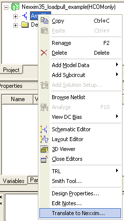
Nexxim Simulator > Translating Serenade Schematics to Nexxim SchematicsDesigner offers a mechanism for translating Circuit (Serenade) schematics directly to Nexxim schematics. Open the Designer project (adsn file) with the Circuit schematic. Right-click on the Circuit design and select Translate to nexxim from the pulldown:
The Translation dialog opens:
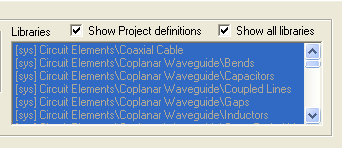
The translator uses a translation map to control the conversion from Circuit components and models to Nexxim components and models. The Translation dialog displays the default translation map, syslib/component1.trt, in black. The listing includes all mapped components, whether or not they are actually in the Circuit design being translated. Components and models that are not yet mapped are shown in red. Saving and Loading Translation Maps In addition to the default translation map, you can define your own maps. Three buttons allow you to create and select maps. • When you have made changes to the map that is currently displayed, the Save map button is enabled. Click Save map to open a Select File dialog. Browse to the directory where you want to save the map, assign it a file name, and click Save. • To make your map the default to use for subsequent translations, click the Set as default map button. • To load a different map, click the Load different map button to open a Select File dialog. Browse to the directory containing the map, select the map file, and click Open. Specifying a Component Mapping The leftmost column of the Translation dialog lists the components in the Circuit schematic. To specify (or change) a mapping for a Circuit component in the Translation dialog, click the button in the Select Translated Component column. If the component is unmapped, the button reads “<UNDEFINED>”; otherwise, the button shows the current mapping. The Select Definition dialog opens. Click the Show all libraries checkbox:
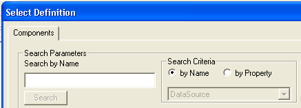
With Show all libraries checked, the display lists Nexxim components with property names that match the ones from the Circuit component. You can search the list by component name or by property name, using the fields in the upper left of the Select Definition dialog:
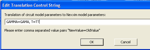
Select the desired Nexxim component and click OK to close the Select Definition dialog and return to the Translation dialog. The Translation dialog now shows the Nexxim component that will be used to translate the Circuit part. The mapped Circuit component name now appears in blue. Controlling Property Mappings Typically, a property on a Circuit component will have a corresponding property (also called a parameter) on the Nexxim component. The names of the corresponding properties may be the same on both Nexxim and Circuit components, or they may differ. By default, the translator copies the value from a Circuit component property to the corresponding parameter in the mapped Nexxim component. When the property names on the Nexxim and Circuit components are different, you must provide the parameter mapping. • On the Translator dialog, click the Parameter translation button for the Circuit component (the parameter translation also applies to any associated Circuit and Nexxim models). The Edit Translation Control String dialog opens:
Enter the translation information as shown in the picture above. Each entry is of the form: NexximName=CircuitName Use commas to separate the entries. Do not put quotes around the entries. For example, if the GAMA property in the Circuit component (or model) corresponds to the GAMMA parameter in the Nexxim component or model, the entry would read: GAMMA=GAMA Properties that have the same name in both Circuit and Nexxim do not need to be listed. These properties will be translated automatically. Handling Models in Circuit and Nexxim Designs Some component instances require the values of parameters from models that are added to the schematic. The translation process must account for the following possibilities: 1. A Circuit component without a model maps to a Nexxim component without a model. 2. A Circuit component without a model maps to a Nexxim component that requires a model. 3. A Circuit component with a model maps to a Nexxim component that also requires a model. 4. The remaining case, where a Circuit component with a model maps to a Nexxim component that does not require a model, is not likely to occur and is not handled by the translator. Case 1: Components without models do not require any special handling. Map the Circuit and Nexxim components as described earlier in this topic. Case 2: When the Circuit component does not have a model but the Nexxim component does have a model, map the components as described earlier. In addition, click the Associated Nexxim Model button for the Circuit component. The Select Definition dialog opens. Select Show all libraries, as described earlier. The listing now shows Nexxim models that are likely candidates. Search through the listing by model name, by parameter name, or by scrolling. Select the Nexxim model, and then click OK to close the Select Definition dialog and return to the Translation dialog. The Translation dialog now shows the Nexxim model to be associated with the Nexxim component when the Circuit component is translated. The “Model Name” field in the Nexxim component and model will be set up so that they will simulate correctly. Case 3: When one or more Circuit components reference a model in the Circuit schematic, the Circuit model must be translated to a Nexxim model directly. The Translation dialog shows the Circuit model as a separate line in the display. Click the Associated Nexxim Model button for the Circuit model. The Select Definition dialog opens. Select Show all libraries, as described earlier. The listing now shows Nexxim models that are likely candidates. Search through the listing by model name, by parameter name, or by scrolling. Select the Nexxim model, and then click OK to close the Select Definition dialog and return to the Translation dialog. The Translation dialog now shows the Nexxim model. When a Circuit component that references the Circuit model is translated, the “Model Name” field in the Nexxim component and the translated model will be set up so that they will simulate correctly. Using Planar EM instead of Nexxim to Simulate a Circuit Component When a component in the Circuit design has a footprint, a checkbox appears in the Use PlanarEM column for that component. Select this checkbox when you want designer to use Planar EM to simulate that component rather than translate it to a Nexxim component. Completing the Translation Process When the mapping is complete, click the Translate button on the Translation dialog. • If you have modified the translation mapping, you will be prompted to save your mapping before proceeding with the translation • If any components are unmapped, a warning appears. Click Yes to proceed, No to abort the translation. Unmapped components are left as-is in the Nexxim schematic. The translation includes any analysis setups present in the Circuit design. The Message Manager window displays the translation status, including any setups that could not be translated. When the translation is complete, the Nexxim design appears in the Schematic editor window and in the Project tree (using a name of the form “circuit_design_name_translated_date).
HFSS视频教程 ADS视频教程 CST视频教程 Ansoft Designer 中文教程 |
|
Copyright © 2006 - 2013 微波EDA网, All Rights Reserved 业务联系:mweda@163.com |
|