|
微波射频仿真设计 |
|
|
微波射频仿真设计 |
|
| 首页 >> Ansoft Designer >> Ansoft Designer在线帮助文档 |
|
Nexxim Simulator > HB Load-Pull Analysis NotesNexxim load-pull analysis computes the frequency-dependent input impedance Z of an ideal tuner, using harmonic balance analysis. The harmonic balance analysis is computed over a spectrum of frequencies specified with the TONES and MAXK entries in the HB statement. The load-pull analysis setup matches the frequencies analyzed by HB to the frequencies of interest specified in the ideal tuner definition. Impedances at Tuner Frequencies The frequencies used to compute the tuner impedance are specified in the TUNER_FREQS entry in the HB statement. The impedances at these frequencies are calculated from the following formula:
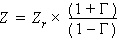
Where Γ (Gamma) is the reflection coefficient of the tuner, and Zr is a reference impedance. The ideal tuner instance parameters define Γ and Zr: Rxxx n1 n2 PORTNUM=val
The impedance calculation is performed over a combined sweep of GAMMA_MAG and GAMMA_ANG. GAMMA_MAG is swept over a range from zero to one, and GAMMA_ANG is swept over a range of zero to 2π (6.283185307) radians. At each sweep point, a harmonic balance is performed to solve for the circuit responses at the calculated tuner impedance. A tuner frequency can be any desired value. If no tuner frequency matches the current HB frequency (or when no tuner frequency is specified), the default impedance parameters RDEF and XDEF are used as the tuner impedance. Impedances at Cluster Frequencies The analysis can incorporate tuner impedances at frequencies of interest other than the actual tuner frequencies. These “cluster” frequencies typically represent harmonics of the tuner frequencies and intermodulation products for multi-tone analyses, but can be any frequencies of interest. The cluster frequencies are specified in the Z_FREQS parameter in the tuner definition. The impedances at these frequencies are specified in the corresponding Z_REAL and Z_IMAG entries. If no cluster frequencies are specified, only the tuner frequencies are analyzed. Deafult Impedances The default tuner impedances are specified in the RDC, RDEF and XDEF entries in the tuner definition. The RDC entry specifies the resistance of the tuner at DC (Frequency = 0). The RDEF entry specifies the default resistance of the tuner. The XDEF entry specifes the default reactance of the tuner. The default impedances are used at any frequency not specified in the TUNER_FREQS or Z_FREQS entries, and when no tuner frequency is supplied. See Ideal Tuner in the Nexxim Components help topics for details on the netlist format for the ideal tuner element. See Nexxim Load-Pull Analysis Netlist Syntax for an example of the ideal tuner netlist format.
HFSS视频教程 ADS视频教程 CST视频教程 Ansoft Designer 中文教程 |
|
Copyright © 2006 - 2013 微波EDA网, All Rights Reserved 业务联系:mweda@163.com |
|


