|
微波射频仿真设计 |
|
|
微波射频仿真设计 |
|
| 首页 >> Ansoft Designer >> Ansoft Designer在线帮助文档 |
|
Nexxim Simulator > Resistor, Ideal Tuner (Netlist Only)
.
Netlist FormatThe ideal tuner defines a port for Load-Pull Analysis. The ideal tuner syntax is based on the Resistor device: Rxxxx n1 n2 PORTNUM=val
n1 is the positive node and n2 is the negative node of the tuner. The current is assumed to flow from n1 through the tuner to n2. The reflection coefficient gamma (G) can be specified using EITHER the GAMMA_REAL/GAMMA_IMAG parameters OR the GAMMA_MAG/GAMMA_ANG parameters, but not both. Typically, the GAMMA_MAG/GAMMA_ANG parameters are used. In the syntax above, the bold brackets [ ] are required when the list of values contains more than one element.
Ideal Tuner Netlist ExampleThe netlist sets up a load-pull analysis by defining netlist parameters ZRho (sample impedance) and ZAng (angle of sample impedance), using these netlist parameters to set an ideal tuner element, and setting up sweeps of the ZRho and ZAng parameters as part of the HB analysis statement. The bolded lines in the example netlist below show the additions for the load-pull analysis, including the ideal tuner element. * Nexxim Load-Pull Netlist Example .PARAM ZRho=1 // Sample impedance for load-pull Notes1. The ideal tuner resistor is required in a netlist-based design only for Load-Pull Analysis, where it is necessary to use a port with a variable reflection coefficient. For schematic designs created within Designer, the load-pull analysis setup creates an ideal tuner automatically on the selected schematic port. For this reason, no Ideal Tuner element is available in the Schematic Editor interface. 2. At the frequencies specified by the TUNER_FREQS list, Nexxim load-pull analysis computes the input impedance Z of an ideal tuner from the following formula:
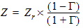
Where G is the reflection coefficient and Zr is the reference impedance of the tuner. The tuner instance parameters define Γ and Zr. The impedance calculation is performed over a combined sweep of GAMMA_MAG and GAMMA_ANG. GAMMA_MAG is typically swept over a range from zero to one, and GAMMA_ANG is swept over a range of zero to 2p (6.283185307) radians. At each sweep point, a harmonic balance is performed to solve for the circuit responses at the calculated tuner impedance. 3. At the frequencies specified in the Z_FREQS list, the impedance is taken from the corresponding Z_REAL and Z_IMAG lists. 4. When no tuner frequency or cluster freqeuency matches the current HB frequency, the default impedance given by RDEF and XDEF is used. 5. The DC resistance is given by RDC for time-domain analyses.
HFSS视频教程 ADS视频教程 CST视频教程 Ansoft Designer 中文教程 |
|
Copyright © 2006 - 2013 微波EDA网, All Rights Reserved 业务联系:mweda@163.com |
|


