|
微波射频仿真设计 |
|
|
微波射频仿真设计 |
|
| 首页 >> Ansoft Designer >> Ansoft Designer在线帮助文档 |
|
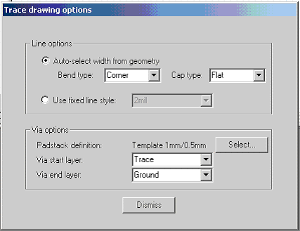
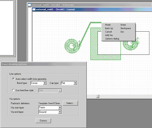
Layout Editor User Guide > Manual Trace GenerationTo set the configuration options for Manual Trace Generation, select Trace > Manual routing from the Draw menu. This opens the model’s Trace Drawing Options dialog:  The following options are available: • Auto-select width from geometry will define the line style by bend type, cap type, and the minimum width of the geometry that is being connected. • Used fixed line style will define the line style from the named line style, which explicitly gives a width as well as bend and cap types. • Padstack definition displays the type of via to use that is specified when you click Select. • Via start layer specifies the start layer for the via. • Via end layer specifies the end layer for the via. Start and end layers automatically switch as vias are placed during manual routing. For example, if the first via leads from trace to ground, the second via, by default, would lead from ground to trace. Begin the trace by selecting two pins, edges, or end points and clicking Traces > Manual routing from the Draw menu. Outputs from the trace are generated as the user clicks on the screen and “grows” the trace from subsequent click-point to click-point. During the trace building process, the user can modify values in the Trace Drawing Options dialog to change the trace that is being generated.  You can switch layers by selecting Add Via from the right-click pop-up menu, and can also use this operation to add a via under the current mouse location. HFSS视频教程 ADS视频教程 CST视频教程 Ansoft Designer 中文教程 |
|
Copyright © 2006 - 2013 微波EDA网, All Rights Reserved 业务联系:mweda@163.com |
|