|
微波射频仿真设计 |
|
|
微波射频仿真设计 |
|
| 首页 >> Ansoft Designer >> Ansoft Designer在线帮助文档 |
|
Layout Editor User Guide > Automatic Trace GenerationTo set the configuration options for Automatic Trace Generation, select Auto-Trace Style from the Layout menu. This opens the Automatic Trace Drawing Options dialog: 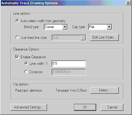 The following options are available: • Auto-select width from geometry will define the line style by bend type, cap type, and the minimum width of the geometry that is being connected. • Used fixed line style will define the line style from the named line style, which explicitly gives a width as well as bend and cap types. • Enable Clearance causes auto-trace to attempt to keep a minimum distance from all geometry, either as a proportion of line width or as an absolute distance. • LineWidth causes auto-trace to attempt to keep a minimum distance, equal to Line Width multiplied by the <number entered>, from all geometry in the layout. • Distance causes auto-trace to keep the defined distance from all geometry in the layout. • Via Options specifies that the selected via type will be used when vias are placed (which occurs when the trace start and end are not on the same layer). • To set additional options, select the Advanced Settings button. This opens the Advanced Auto-Trace Options dialog: 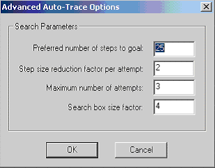 The following options are available: • Preferred number of steps to goal is divided into the distance from start to end in order to calculate the step size for the trace grid. In general, smaller step sizes (that is, larger numbers of steps) mean slower performance but better solutions, due to the finer control of the trace path. Note, however, that the step size can never be less than the line width of the generated path. • Step size reduction factor per attempt is divided into the step size, if a path avoiding obstacles is not found. Then the algorithm is attempted again. Attempts will continue until the step size is less than the line width or until Maximum number of steps is reached. • Maximum number of attempts specifies the upper limit of retry attempts for the trace. • Search box size factor is multiplied by the distance from the start to end in order to set the maximum search box size for the trace. As a result, the auto-generated path stays inside the dimensions of the calculated search box. After configuring options for Automatic routing, begin the trace by selecting two pins, edges, or end points and clicking Traces > Automatic routing from the Draw menu. Outputs from the trace are generated and include lines and vias that connect input while avoiding obstacles. Note that vias are added when start/end points do not lie on the same layer, and via positions are chosen so they do not intersect metal. As a result, vias will lie over geometry on ground layers (which are negatives). 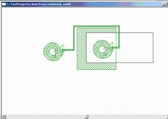
HFSS视频教程 ADS视频教程 CST视频教程 Ansoft Designer 中文教程 |
|
Copyright © 2006 - 2013 微波EDA网, All Rights Reserved 业务联系:mweda@163.com |
|


