|
微波射频仿真设计 |
|
|
微波射频仿真设计 |
|
| 首页 >> Ansoft Designer >> Ansoft Designer在线帮助文档 |
|
Layout Editor User Guide > Assigning Reference PortsYou can assign reference ports using the Draw > Port > Assign Reference command. Both selected edges and vias are changed to ports: • Selected edges become edge ports • Selected vias become pins You can assign reference ports using any of the following scenarios.
Padstack/Padstack 1. With two padstack instances selected.  2. Select Draw > Port > Create  3. The first padstack selected becomes the port, and the second becomes the reference.
Edge/Edge 1. With two non-linear edge groups selected on the same layer.  2. Select Draw > Port > Create  3. The first edge selected becomes the port, and the second becomes the reference.
Edge/Padstack 1. With an edge and a padstack selected. 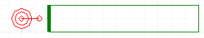 2. Select Draw > Port > Create 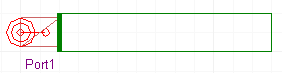 3. The first edge becomes the port, and the second becomes the reference.
Port/Padstack 1. With an existing port and a padstack selected. 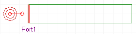 OR  2. Select Draw > Port > Assign Reference 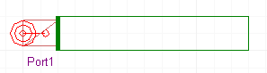 OR  3. The padstack becomes the reference for the port.
HFSS视频教程 ADS视频教程 CST视频教程 Ansoft Designer 中文教程 |
|
Copyright © 2006 - 2013 微波EDA网, All Rights Reserved 业务联系:mweda@163.com |
|


