|
微波射频仿真设计 |
|
|
微波射频仿真设计 |
|
| 首页 >> Ansoft Designer >> Ansoft Designer在线帮助文档 |
|
Importing and Exporting Data > Importing GDSII Format FilesSee the introductory topic Importing 2D Model Files into the Layout Editor for the initial steps in the process of importing 2D data into the Layout Editor. After you select a 2D model file to import, the following dialog opens: 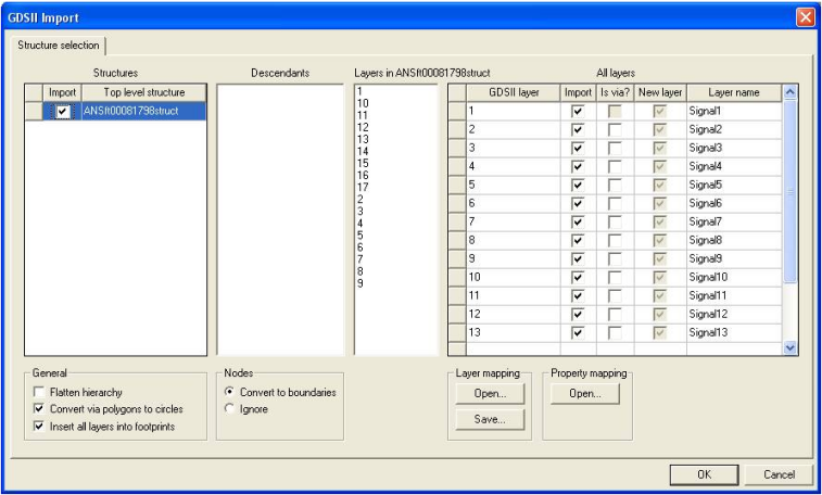
1. The GDSII file may contain several top level structures. Click on a structure name in the GDSII Structures panel to highlight it. Clicking on the Import checkbox in the GDSII Structures panel both highlights the structure and selects that top-level structure to be imported. When multiple structures are imported, Designer creates multiple designs under the current project, one for each of the GDSII structures. 2. The GDSII file is hierarchical and may contain many sub-layouts. The Descendants panel shows the sub-layouts in the selected top-level designs. 3. The Layers in structurename panel shows the layers for the (most recently) highlighted top level structure [structurename]. GDSII layers are identified by layer numbers. 4. The All layers panel lists all the layers from all the structures in the file. Use the Import check boxes in the All layers panel to select the layers to import. You can drag and drop the layers in the list to change the vertical stackup of layers. 5. Use the “Is via?” checkbox to identify a layer as a “via layer” that can be used to create vias in the design. When a GDSII layer is marked to be a via, the objects on the layer will be used to create 2D vias that connect from the previous layer to the following layer (as found in the grid control of the import dialog). The top and bottom layer cannot be marked as via layers because there are not two layers to connect, and there also may not be more than one consecutive via layer. 6. Use the New layer checkbox to have Designer create a new layer in the design for this layer. 7. Use the Layer names column to rename a layer to an existing name in the design. Select from a drop down list of choices or type in a new layer name. 8. GDSII supports nodes and boundaries as separate data types. Normally, boundaries represent polygons. Designer can either convert objects that use the nodes data type to boundary types, or can ignore them. Use the Nodes radio buttons to select Convert to boundary or Ignore. The default is to convert data type nodes to data type boundary. 9. Select the Convert via polygons to circles checkbox as desired (default is selected). When this option is in effect, polygons on layers marked as via layers (using the Is via? option discussed earlier) are converted to circles to simplify via creation. Designer finds the center of the polygon and treats is as the center of the circle. The radius is the distance to one vertex from the center. A polygon is converted to a circle only when the difference in area between the polygon and the circle is less than 10 percent of the area of the circle. 10. When importing into a Nexxim design, the Flatten hierarchy checkbox is used to request that the imported designs are flat or are created with hierarchy. When created with hierarchy, descendants of the imported design are used to create components. (Importing into a Planar EM design is always done with hierarchy flattened.) 11. In GDSII properties are identified by number. The GDSII file specifies the property values for numbered properties within all top-level structures. Before importing a GDSII file into Designer, you can create a property mapping file using a text editor. The property mapping file must have a .propmap suffix. The property mapping file lists the GDSII property numbers and the corresponding Designer property names without any header or comments, for example: 5 textprop To view a property map file, click the Open button in the Property Mapping panel. The File Open dialog appears so you can browse to the directory where the file resides. 12. If desired, you can create a mapping of the GDSII layer numbers to layer names in the design stackup. Two alternatives are available for creating the mapping. For details see Layer Mapping Files. • Use a text editor to create a text file that maps the GDSII layer numbers to layer names in the stackup. This layer mapping file has .layermap suffix. The format is the same as the one shown above for the property mapping file. Click the Open button in the Layer Mapping panel to locate and open an existing layer mapping file. • Use a text editor to create a text file that maps the GDSII layer numbers to layer names in the stackup. This layer mapping file has a .tech suffix. The format of a .tech format layer mapping file list includes the layer number and corresponding layer name, color, elevation and thickness. The tech file should specify layers in nm units. • Instead of using a text editor to create a layer mapping file, click the Save button in the Layer Mapping panel to create a layer map based on the existing stackup names and GDSII layer numbers. 13. Click OK. The file is imported into the active Layout window.
HFSS视频教程 ADS视频教程 CST视频教程 Ansoft Designer 中文教程 |
|
Copyright © 2006 - 2013 微波EDA网, All Rights Reserved 业务联系:mweda@163.com |
|


