|
微波射频仿真设计 |
|
|
微波射频仿真设计 |
|
| 首页 >> Ansoft Designer >> Ansoft Designer在线帮助文档 |
|
Dynamic Links and Solver On Demand > Add an HFSS N-Port ModelPlease note that in HFSS, differential terminal data is transferred to Designer as underlying terminal data — which is not differential. For this reason, differential data plotted in HFSS may not agree with raw terminal data plotted in Designer.
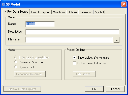
1. To add an HFSS N-Port model, first open the design. Select Project > Add Model > Add HFSS Model. Designer will pause for a few seconds while HFSS starts up. The following dialog will then be displayed:
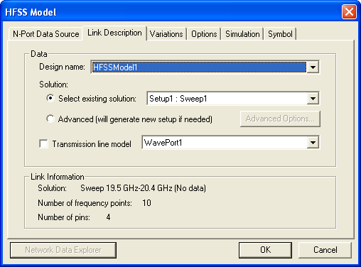
The following controls are available: • Enter a Model Name. A Description is optional. • Use the File name field to browse and select an HFSS design to be the source for the dynamic link. • Use the browse button (...) to locate an existing HFSS design to open. • Use the Mode area to choose from the available modes supported for an HFSS subcircuit: — Parametric Snapshot — Dynamic Link (default) • If enabled, set the Project Options: — Save project after simulate specifies that the project will be saved and closed once its data is accessed and the simulation is complete. — Unload project after use specifies that the project will be unloaded once its data is accessed and the dialog box is closed. — Edit Project brings up the HFSS application. • Network Data Explorer — Allows you to view solution data by opening the Network Data Explorer. 2. Click the Link Description tab. This tab allows you to select the HFSS solution setup to use in the dynamic link. The Link Information panel at the bottom of the tab shows the selected frequency points.
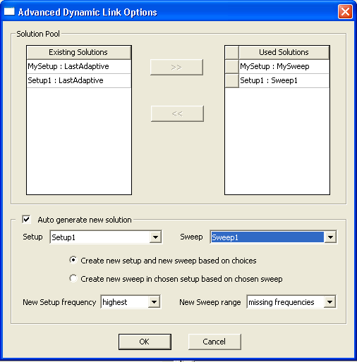
The following controls are available: • Design name specifies the top-level design in the HFSS project. • Solution specifies the solution to be used for the HFSS subcircuit. • Click Select existing solution to enable the selection field. Select an HFSS solution from the pulldown. • Click Advanced to specify a custom setup using the Advanced Options button (see next step). • Transmission line model specifies that the model specified in the pull-down menu at right will be used for transmission lines (HFSS import only) • Network Data Explorer — Allows you to view solution data by opening the Network Data Explorer. 3. When Advanced setup has been selected, the Advanced Options button becomes active. Click on the Advanced Options button to open the Advanced Dynamic Link Options dialog:
The following controls are available: • Select one or more of the Existing Solutions to use in the simulation. These frequency ranges will be simulated by HFSS. Nexxim or system can extrapolate or interpolate the simulation to desired frequencies that are not covered by these setups. • Click Auto generate new solution for HFSS to calculate missing frequency ranges required by Nexxim/System. • Select the desired Setup and Sweep. • Use Create new setup to specify that a new setup specification will be defined in HFSS. This generates a new adaptive mesh for the HFSS analysis. Next, use the New Setup frequency field to select the new adaptive frequency for mesh generation: “highest” or “middle”. • Use Create new sweep to specify that a new sweep specification will be defined using an existing setup in HFSS. This uses the existing adaptive mesh for the HFSS analysis, which saves simulation time. Next, select a New Sweep range: choose “all frequencies” to simulate the entire range of frequencies desired by Nexxim/System, or choose “missing frequencies” to simulate only the frequencies not listed in the Used Solutions list.
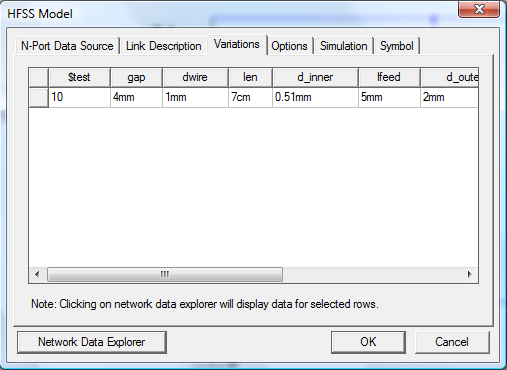
4. Click OK to close the Advanced Dynamic Link Options dialog and return to the HFSS Model dialog. Next, click on the Variations tab:
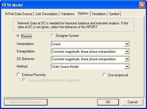
The Variations tab is used to view the data for selected rows by clicking Network Data Explorer which opens the Network Data Explorer. 5. Next, click on the Options tab:
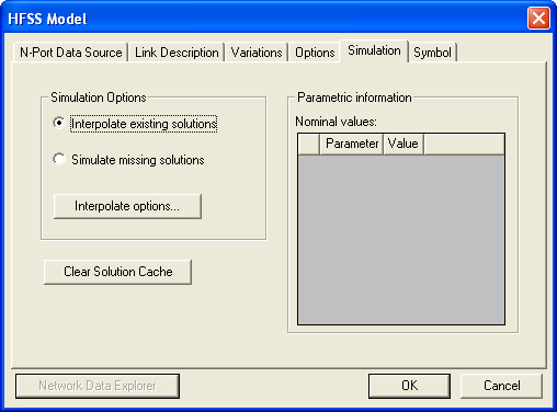
The following controls are available: • Nexxim/Designer System — Sets the NPort type • Interpolation — Specifies the interpolation as Step or Linear • Extrapolation — Specifies the type of extrapolation that is to be used with the NPort • DC Behavior — Specifies the type of DC behavior that is to be used with the NPort • Method — Specifies the method used to convert frequency domain data to the time domain • Enforce Passivity — Enforces a passivity check which tests whether the S-parameter data is passive or not. Passive devices can only dissipate, or temporarily store energy, but never generate it. • Use reciprocal — Computes the inverse, or reciprocal, at each frequency so that the N-port can be used for de-embedding • Network Data Explorer — Allows you to view solution data by opening the Network Data Explorer. 6. Next, click on the Simulation tab:
The following controls are available: • Interpolate existing solutions interpolates existing solution data. When Interpolate existing solutions is not selected, Designer simulates or calculates any solution data that is needed. • Simulate missing solutions asks HFSS or Q3D to simulate, if the solution is not available. • Clear Solution Cache when clicked will immediately clear the solution cache memory. • Network Data Explorer — Allows you to view solution data by opening the Network Data Explorer.
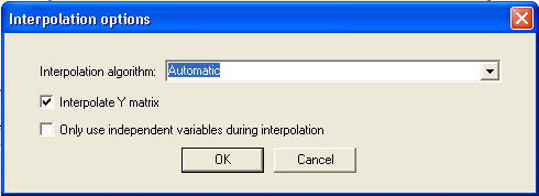
7. Click Interpolation options to open the following dialog:
The following options are available: • Click the down arrow in the Interpolation algorithm field to select an interpolation algorithm option: Automatic — Linear interpolation is used if a full grid of solutions is present, otherwise Inverse Least Squares with Shadowing and Hyperplanes is used. Linear — When a full grid of solutions is available, the cube of solutions which surrounds the solution to be interpolated is located. The corners of this cube are linearly averaged to determine the interpolated solution. If a full grid is not available, an error is reported and the interpolation fails. Inverse Least Squares with Shadowing and Hyperplanes — Least squares interpolation with shadowing and hyperplanes. Inverse Least Squares with Shadowing, no Hyperplanes — Least squares interpolation with shadowing, but no hyperplanes. • Interpolate Y matrix uses the Y matrix as the basis for interpolation. When Interpolate Y matrix is not selected, the S matrix is used as the basis. Interpolate Y matrix is selected by default. Circuit particulars determine which basis (S or Y) will yield better results, and it is not possible to decide beforehand which one will work best. • Only use independent variables
during interpolation suppresses the calculation of dependent variable
values during interpolation.
8. After choosing interpolation settings, click OK to close the Interpolation Options dialog. 9. Click OK to close the HFSS Model dialog.
HFSS视频教程 ADS视频教程 CST视频教程 Ansoft Designer 中文教程 |
|
Copyright © 2006 - 2013 微波EDA网, All Rights Reserved 业务联系:mweda@163.com |
|