
The Yagi antenna
The Yagi or Yagi-Uda RF antenna or aerial is one of the most successful RF antenna designs for directive applications. It is used in a wide variety of applications where an RF antenna design with gain and directivity is required. It has become particularly popular for television reception, but it is used in very many other applications where an RF antenna design is needed that has gain.
The full name for the antenna is the Yagi-Uda antenna. It was derives it name from its two Japanese inventors Yagi and his student Uda. The RF antenna design concept was first outlined in a paper that Yagi himself presented in 1928. Since then its use has grown rapidly to the stage where today a television antenna is synonymous with an RF antenna having a central boom with lots of elements attached.
The Yagi antenna
The Yagi RF antenna design has a dipole as the main radiating or driven element. Further "parasitic" elements are added which are not directly connected to the driven element. Instead they pick up power from the dipole and re-radiate it such a manner that it affects the properties of the RF antenna as a whole.
Basic concept of a Yagi antenna
The parasitic elements of the Yagi antenna operate by re-radiating their signals in a slightly different phase to that of the driven element. In this way the signal is reinforced in some directions and cancelled out in others. It is found that the amplitude and phase of the current that is induced in the parasitic elements is dependent upon their length and the spacing between them and the dipole or driven element.
Using a parasitic element it is not possible to have complete control over both the amplitude and phase of the currents in all the elements. This means that it is not possible to obtain complete cancellation in one direction. Nevertheless it is still possible to obtain a high degree of reinforcement in one direction and have a high level of gain, and also have a high degree of cancellation in another to provide a good front to back ratio.
To obtain the required phase shift an element can be made either inductive or capacitive. If the parasitic element is made inductive it is found that the induced currents are in such a phase that they reflect the power away from the parasitic element. This causes the RF antenna to radiate more power away from it. An element that does this is called a reflector. It can be made inductive by tuning it below resonance. This can be done by physically adding some inductance to the element in the form of a coil, or more commonly by making it longer than the resonant length. Generally it is made about 5% longer than the driven element.
If the parasitic element is made capacitive it will be found that the induced currents are in such a phase that they direct the power radiated by the whole antenna in the direction of the parasitic element. An element which does this is called a director. It can be made capacitive tuning it above resonance. This can be done by physically adding some capacitance to the element in the form of a capacitor, or more commonly by making it about 5% shorter than the driven element.
It is found that the addition of further directors increases the directivity of the antenna, increasing the gain and reducing the beamwidth. The addition of further reflectors makes no noticeable difference.
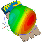
The antenna exhibits a directional pattern consisting of a main forward lobe and a number of spurious side lobes. The main one of these is the reverse lobe caused by radiation in the direction of the reflector. The antenna can be optimised to either reduce this or produce the maximum level of forward gain. Unfortunately the two do not coincide exactly and a compromise on the performance has to be made depending upon the application.
Polar diagram of the Yagi antenna
Gain
The gain of a Yagi antenna is governed mainly by the number of elements in the particular RF antenna. However the spacing between the elements also has an effect. As the overall performance of the RF antenna has so many inter-related variables, many early designs were not able to realise their full performance. Today computer programmes are used to optimise RF antenna designs before they are even manufactured and as a result the performance of antennas has been improved.
Feed impedance
It is possible to vary the feed impedance of a Yagi antenna over a wide range. Although the impedance of the dipole itself would be 73 ohms in free space, this is altered considerably by the proximity of the parasitic elements. The spacing, their length and a variety of other factors all affect the feed impedance presented by the dipole to the feeder. In fact altering the element spacing has a greater effect on the impedance than it does the gain, and accordingly setting the required spacing can be used as one design technique to fine tune the required feed impedance. Nevertheless the proximity of the parasitic elements usually reduces the impedance below the 50 ohm level normally required. It is found that for element spacing distances less than 0.2 wavelengths the impedance falls rapidly away.
To overcome this, a variety of techniques can be used. One is to use a folded dipole for the driven element. This provides an increase in impedance of around four times dependent upon the ratio of the thicknesses of the basic dipole conductor and the "fold" conductor. Other techniques involve using gamma matches, delta matches, baluns and the like. Delta matches can be very convenient. They involve "fanning out" the connection to the driven element. This method has the advantage that the driven element does not need to be broken to apply the feed as shown. As this is really applicable to a balanced feeder, a balun is required if coaxial cable is to be used.
A gamma match is another alternative that is often used. The outer or braid of the coax feeder is connected directly to the centre of the driven element. This can be done because the RF voltage at the centre is zero at this point. The inner conductor of the feeder carrying the RF current is taken out along the driven element. The inductance of the arm is then tuned out by the variable capacitor. When adjusting the RF antenna design, both the variable capacitor and the point at which the arm contacts the driven element are adjusted. Once a value has been ascertained for the variable capacitor, its value can be measured and a fixed component inserted if required.
Summary
The Yagi antenna is a particulary useful form of RF antenna design. It is widely used in applications where an RF antenna design is required to provide gain and directivity. In this way the optimum transmission and reception conditions can be obtained.
thank you !!
不错 谢谢、
相关文章:
- 问个Yagi-Uda天线的问题(05-08)
- 請問如何縮小YAGI 天線的尺寸? (05-08)
- 哪位好心人有文章Takeshima(x-band omni-directional double-slot array antenna)?(05-08)
- 求Antenna theory and design,(美)埃利奥特(Elliott,Robert S.)编著(05-08)
- 请问在哪能找见这篇文章《Numerical Modeling of RCS and Antenna Problems》?(05-08)
- Need the three papers on broadband antennas(05-08)