


- 1
- 2
- 3
- 4
Example Projects
Helical Antenna
Description - a coax fed helical antenna with a dielectric support on a finite ground plane. The antenna is designed to run at 3.5 GHz. A smaller virtual object is defined as the integration surface for radiated field calculations. This is surrounded by an air box with a radiation boundary.*
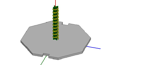
Model - the support is made of Teflon and the ground has as thickness of 0.5 in. The coax port is internal and is capped by a conducting object. You can create a helix similar to this by using Draw>User Defined Primitive>SysLib>Segmented Helix.
Setup - adapt at 3.5 GHz and use mixed order for Order of Basis function. Since this model has open air regions and the tightly spaced helix it is a good choice for mixed order.
Note |
To view a port or boundary, select the desired item in the Project Tree. It is then highlighted in the Model window and the properties will be displayed in the Properties window. Selecting an object in the History tree will also display its properties. *For a further discussion on using integration surfaces and for more on creating sample antenna designs, see the antenna design kit at www.ansoft.com/hfssantennadesignkit. |
Post Processing
After solving, you can view solution data by right-clicking on Setup1 and selecting Profile to display the Solution dialog. You also view the Solution tabs for Convergence, Matrix Data, and Mesh Statistics.
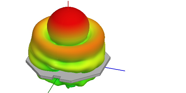
To view 3D plot of the antenna gain, look in the Project Tree under Results and double click on 3D Polar Plot 1. To overlay the 3D plot on the model, click HFSS>Fields>Plot Fields>Radiation Field to display the Overlay radiation field dialog. Check Visible for 3D Polar Plot 1, and set the transparency and scale as desired.
To view a 2D plot of the total gain, in the Project tree, double-click on Results - Radiation Pattern 1.
To view a 2D plot of the circular polarization pattern for this antenna in the f = 0o cut, in the Project tree, double click Results - Radiation Pattern 2.
You can add markers to the Radiation Pattern plots by right-clicking on the plot window and choosing Marker>Add Marker.
-

国内最全面的HFSS培训课程,包含7套视频教程和2本教材,资深专家讲解,视频操作演示,结合最新工程案例,让HFSS学习不再难...【详细介绍】
