Technical Notes > Radiated Fields > Array Factors
Custom Arrays
Once you have imported the array factor information from a text file, HFSS uses (eq. 8) to compute the array factor. When a custom array is defined, no scan direction is set and the array factor phase weights are those specified on an element-by-element basis in the geometry file.
The text file must have the following format. Coordinate values are assumed to be model units, and phase and amplitude are in SI units (radians and volts respectively):
N
x_1 y_1 z_1 A_1 P_1
x_2 y_2 z_2 A_2 P_2
...
...
x_N y_N z_N A_N P_N
where
• x_1 is the x-coordinate position of the first element.
• y_1 is the y-coordinate position of the first element.
• z_1 is the y-coordinate position of the first element.
• A_1 is the amplitude weight of the first element. Amplitude references voltage.
• P_1 is the phase weight for the first element. Phase references radians.
Following is an example of a square 3 x 3 custom array geometry defined in a text file. The array elements are uniformly weighted and separated from one another in the x- and y-directions by 0.6729 user units.
! first line is a count of cells
9
! then [x,y,z] position of each cell
! and amplitude and phase
! default units for position are model units
! default units for amplitude is Volts
! default units for phase is radians
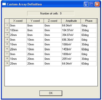
0 0 0 64.04mV 0
10cm 0 0 184.97mv 30deg
20 0 0 394.87mv 60deg
0 10 0 696.36mv 0
10 10 0 1.066 30deg
20 10 0 1.459 60deg
0 20 0 1.808 0
10 20 0 2.051 30deg
20 20 0 64.04mv 60deg
The information will appear as follows in the Custom Array Definition window:

-

国内最全面的HFSS培训课程,包含7套视频教程和2本教材,资深专家讲解,视频操作演示,结合最新工程案例,让HFSS学习不再难...【详细介绍】


