


- 1
- 2
- 3
- 4
ANSYS Workbench Integration Overview > ANSYS EM CAD Integration through Workbench
CAD Integration and Geometry Sharing
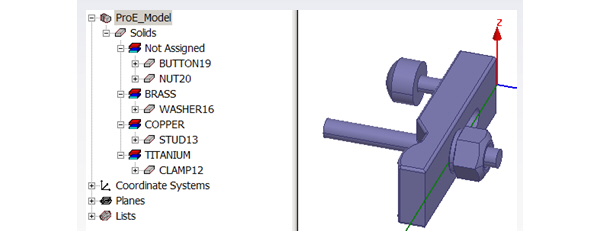
CAD model comes into ANSYS Electromagnetics as User Defined Model (UDM).
The input to ANSYS Electromagnetics from CAD is:
• Geometry/Topology with persistent IDs
• CAD parameters
• Material assignment
• Attributes like name, and color
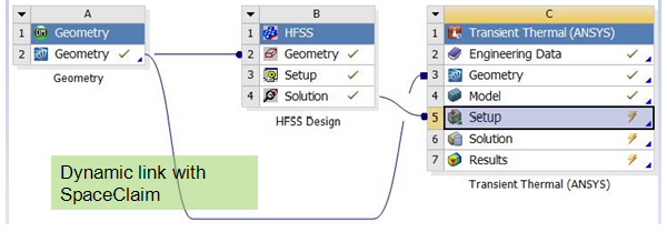
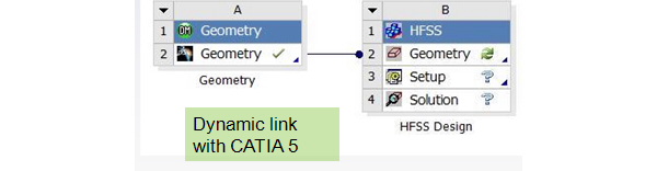

For example, in Workbench, a Pro/E Model can be linked to ANSYS.

The geometry can then be viewed in HFSS as a UDM.
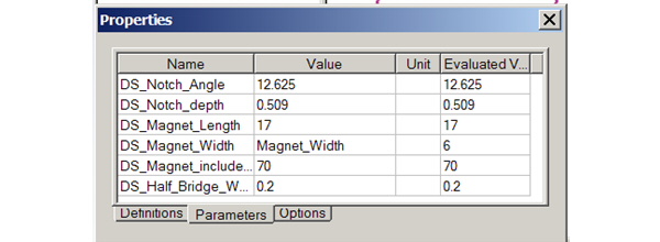
The CAD or WB model parameters appear in the Workbench:
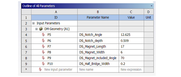
Though the ANSYS Electromagnetics CAD Integration, the linked UDM includes the same parameters.
Related Topics
ANSYS EM CAD Integration Through Workbench
Bi-Directional CAD Integration
CAD Integration Model Edits
Multiple Geometry Links for CAD Integration
CAD Integration Functionality
Healing with CAD Integration
Important Geometry Options for CAD Integration
-

国内最全面的HFSS培训课程,包含7套视频教程和2本教材,资深专家讲解,视频操作演示,结合最新工程案例,让HFSS学习不再难...【详细介绍】
