


- 1
- 2
- 3
- 4
Assigning Boundaries
Assigning Master Boundaries
Master and slave boundaries enable you to model planes of periodicity where the E-field at every point on the slave boundary surface is forced to match the E-field of every corresponding point on the master boundary surface to within a phase difference. The transformation used to map the E-field from the master to the slave is determined by specifying a coordinate system on both the master and slave boundaries.
To assign a Master boundary:
1. Select a surface on which to assign the boundary and click HFSS>Boundaries>Assign>Master to bring up the Master Boundary dialog box.
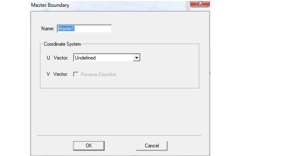
2. You must specify the coordinate system in the plane on which the boundary exists. First draw the U vector of the coordinate system. HFSS uses the U vector that you draw and the normal vector of the boundary face to calculate the Vvector. If necessary, you can reverse the direction of the V vector.
a. Select New Vector from the U Vector pull-down list.
The Master Boundary dialog box disappears while you draw the U vector.
b. Select the U vector’s origin, which must be on the boundary’s surface, either by:
• Clicking the point for the vector origin.
• Typing the point’s coordinates in the X, Y, and Z boxes.
c. Select a point on the u-axis to indicate the U vector direction.
The Master Boundary dialog box reappears and the model display shows the U vector and V vector as red and blue arrows respectively.
d. If you need to reverse the direction of the V vector, select Reverse Direction.
HFSS will compute the E-field on this boundary and map it to the slave boundary using the transformation defined by the master and slave coordinate systems.
Related Topics
Technical Notes: Master and Slave Boundaries
Assigning Slave Boundaries
Getting Started Guides: Floquet Ports
-

国内最全面的HFSS培训课程,包含7套视频教程和2本教材,资深专家讲解,视频操作演示,结合最新工程案例,让HFSS学习不再难...【详细介绍】
