|
微波射频仿真设计 |
|
|
微波射频仿真设计 |
|
| 首页 >> Ansoft Designer >> Ansoft Designer在线帮助文档 |
|
Transmission Line Designer > Lange Coupler
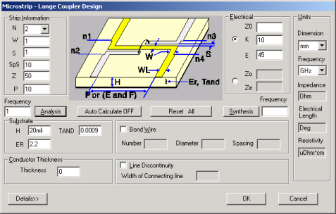
Synthesis and AnalysisSynthesis of a Lange coupler proceeds by first selecting the number of strips for the desired structure. Two options exist for synthesis: — Specify impedance, Z0, and the coupling coefficient, K. — Specify the even-mode impedance, Ze, and the odd-mode impedance, Zo. • The substrate parameters H, and ER must be entered prior to clicking the Synthesis button. The width of the strips, Width, and the spacing between them, Spacing, will be computed. Also, the alternate electrical option set will be computed (e.g., if Z0 and K are entered, Ze and Zo will be computed). • For analysis, the parameters Width, Spacing, H, ER and either Physical Length or Frequency must be entered prior to clicking the Analysis button. The electrical properties, Z0, K, Zo, and Ze will be computed. • Conversion from electrical length, E, to physical length, P, can be performed by entering a value for E and the frequency, Frequency. Click Synthesis to compute P. Similarly, to convert from physical length to electrical length, enter values for P and Frequency and click Analysis to compute E.
Dielectric SubstratesA dielectric substrate is defined by the parameters H, ER, and TAND. The substrate is assumed to be lossless unless TAND is specified and greater than zero.
Conductor MetallizationThe default conductor used for analysis is gold whose resistivity is 2.44 mohm-cm. The thickness of the metal can be specified using the Thick parameter in the substrate group. The calculation uses the thickness for loss and impedance calculations.
Frequency Sweep OptionsA frequency sweep can be performed to determine the response of the coupler over frequency. Type Start Stop Step (e.g., 4 6 5) and click Analysis.
ExampleTo select the Lange coupler, select TRL on the Product menu, click Microstrip, and click Lange Coupler. Set the units to mil and GHz. We will use the following parameters for synthesizing a 4 strip, 3-dB coupler at 10 GHz:
Click the Synthesis button to determine the coupled line parameters:
***** LANGE SYNTHESIS *****
COUPLING IMPEDANCES (OHMS) SUBSTRATE FULL STRIPS DB EVEN ODD COUPLER ER H(mils) NO. T(mils) W(mils) S(mils) 3.00 120.91 20.68 50.00 10.00 25.0000 4 0.20000 1.6545 2.0000
To include the effects of a bond wire and connecting
line parasitics, enter the following:
Clicking Analysis yields the following:
***** LANGE ANALYSIS *****
SUBSTRATE: THICKNESS = 25.0000 mils DIELECTRIC CONSTANT = 10.0000 LOSS TANGENT = 0.00000
STRIPS: NUMBER = 4 WIDTH = 1.6545 mils SPACING = 2.0000 mils THICKNESS = 0.2000 mils SUBSTRIPS = 10
PARASITICS: NO. PARALLEL WIRES = 3 BOND WIRE DIAMETER = 0.8000 mils WIRE SEPARATION = 2.0000 mils WIDTH OF 50 OHM LINE = 24.5000 mils
W/H =0.066181 S/H =0.079999 W/H =0.071646 S/H =0.074534 EFFECTIVE VALUES DUE TO FINITE THICKNESS
*** DC CHARACTERISTICS Z(0) = 50.00 Ohms ZOE OHMS ZOO OHMS COUP DB Z(0) EFFKE EFFKO VE M/SEC VO M/SEC 131.56 22.81 3.04 54.79 6.378 5.502 1.1870E+8 1.2781E+8
*** CHARACTERISTICS WITH DISPERSION CENTER FREQUENCY = 10000.0 MHZ ZOE OHMS ZOO OHMS COUP DB Z(0) EFFKE EFFKO VE M/SEC VO M/SEC 134.08 23.18 3.03 55.75 6.380 5.510 1.1869E+8 1.2771E+8
EVEN MODE ATTENUATION ODD MODE ATTENUATION db/in db/in 0.6087 2.1903 DIELECTRIC + CONDUCTOR
EFFECTIVE DIELECTRIC CONSTANT OF COUPLER = 5.9371 ESTIMATED COUPLING LENGTH = 121.098 mils
INDUCTANCE PER CROSSOVER LOCATION = 0.12526 nH RESISTANCE PER CROSSOVER LOCATION = 0.04920 Ohms
*** RESPONSE WITH DISPERSION AND PARASITICS FREQ. REFL. VSWR RET LOSS COUPL. PHASE THRU LOSS PHASE ISOLAT (MHz) COEFF (dB) (dB) (Deg) (dB) (Deg) (dB) 10000 0.068 1.15 -23.3 3.23 -0.6 -3.11 -90.2 -24.66
DUE TO PARASITICS, THE CENTER FREQUENCY HAS SHIFTED DOWN FROM 10000 MHZ
To perform a frequency analysis from 4 GHz to 12 GHz in steps of 1 GHz, type 4 12 1 in the Frequency box. Then add coupling length P = 121.098 mil. The last part of the output will contain the analysis at each frequency. The 10 GHz center frequency analysis point is used to compute the quasistatic characteristics and reused at each analysis frequency.
FREQUENCY ANALYSIS OF COUPLER
FREQ. REFL. VSWR RET LOSS COUPL. PHASE THRU LOSS PHASE ISOLAT (MHz) COEFF (dB) (dB) (Deg) (dB) (Deg) (dB) 4000 0.078 1.17 -22.1 5.99 42.2 -1.56 -45.6 -23.92 5000 0.081 1.18 -21.8 4.89 33.7 -2.02 -54.5 -23.42 6000 0.081 1.18 -21.8 4.17 26.0 -2.42 -62.5 -23.30 7000 0.079 1.17 -22.1 3.70 18.9 -2.74 -69.9 -23.41 8000 0.076 1.16 -22.4 3.41 12.2 -2.97 -76.9 -23.69 9000 0.072 1.16 -22.8 3.26 5.7 -3.10 -83.6 -24.11 10000 0.068 1.15 -23.3 3.23 -0.6 -3.11 -90.2 -24.66 11000 0.065 1.14 -23.8 3.33 -7.1 -3.02 -96.9 -25.34 12000 0.060 1.13 -24.4 3.56 -13.8 -2.81 -103.8 -26.03
Electrical Length [Eeff=(Effo+Effe)/2] = 35.78 deg
HFSS视频教程 ADS视频教程 CST视频教程 Ansoft Designer 中文教程 |
|
Copyright © 2006 - 2013 微波EDA网, All Rights Reserved 业务联系:mweda@163.com |
|