|
微波射频仿真设计 |
|
|
微波射频仿真设计 |
|
| 首页 >> Ansoft Designer >> Ansoft Designer在线帮助文档 |
|
HFSS and Planar EM Simulators > Creating a BondwireBondwires are created using the Designer Link plug-in primitive framework. To create a bondwire:
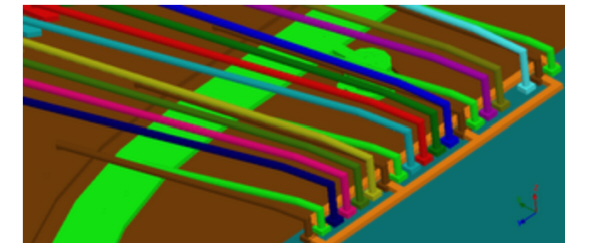
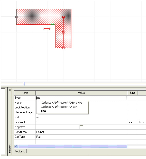
1. Create a line via Draw > Primitive > Line. 2. Toggle the Footprint Property Type from Line to Cadence APD/Allegro:APDPath 3. Set the Bondwire properties to render the profile: • PlacementLayer: Sets the layer for 2D primitive rendering. Bondwires are 3D elements, so this layer does not affect the solved geometry; it is only used for visualization purposes. Often, PlacementLayer is used to group bondwires according to profile usage. • Net: Sets the net attribute for the primitive. • Start Layer: Controls the starting elevation for the profile's 3D rendering. • End Layer: Controls the final elevation for the profile's 3D rendering. • Profile: Selects the profile definition from which the bondwire geometry will be created. The dialog renders a context-sensitive example, using the active selection's layer settings and point list. • Path Width: Sets the diameter of the 3D profile. • Point List: The first point sets the profiles beginning location in X and Y. The last sets the ending location. 4. Loop orientation is set using the PlacementLayer's top/bottom association (Layout > Layers). 5. The resulting 3D geometry can be visualized in the 3D Layout view. 
Any line may be converted to a compatible plug-in through the “Type” property

Available types will depend on the configured external Designer Links. HFSS视频教程 ADS视频教程 CST视频教程 Ansoft Designer 中文教程 |
|
Copyright © 2006 - 2013 微波EDA网, All Rights Reserved 业务联系:mweda@163.com |
|