淘宝官方店     推荐课程     在线工具     联系方式     关于我们  


微波射频仿真设计   Ansoft Designer 中文培训教程   |   HFSS视频培训教程套装


Agilent ADS 视频培训教程   |   CST微波工作室视频教程   |   AWR Microwave Office

          首页 >> Ansoft Designer >> Ansoft Designer在线帮助文档


Ansoft Designer / Ansys Designer 在线帮助文档:


Nexxim Simulator >
Nexxim Component Models >
Independent Sources >
   Voltage Source, AM (Netlist Only)       

Voltage Source, AM (Netlist Only)


AM Voltage Source Netlist Format

The netlist format for amplitude-modulated, time-varying (AM) voltage source is:

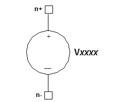
Vxxxx n+ n- AM (sa oc fm fc [td])

n+ is the positive node and n- is the negative node of the voltage source. Parameters in parentheses are positional. The first four parameters must be present in the order given.


Note 

The AM voltage source is available for use in netlists, but is not supported in the Components window of the Designer Schematic Editor.


AM Voltage Source Parameters

Parameter

Description

Unit

Default

sa

Signal amplitude

Volt

0.0

oc

Offset constant applied to the modulation amplitude

None

0.0

fm

Modulation frequency

Hertz

1/TSTOP

fc

Carrier frequency

Hertz

0.0

td

Propagation delay before the start of the signal

Second

0.0


AM Voltage Source Netlist Example

* AM Voltage Source netlist example
* To visualize the interaction of sa (signal amplitude)
* and oc (offset constant)
* swap the next two lines by moving the comment mark (*),
* analyze, create reports

* V1 1 0 AM (80 0 5e6 1e9 0)

V1 1 0 AM (20 4 5e6 1e9 0)

R1 1 0 1

.TRAN 1e-10 1e-6

.PRINT tran V(1)

.END

Notes

1. The AM voltage source output is calculated as follows:

output = sa ´ {oc + sin[2p ´ fm ´ (time - td)]} ´ sin[2p ´ fc ´ (time - td)]


HFSS视频教学培训教程 ADS2011视频培训教程 CST微波工作室教程 Ansoft Designer 教程

                HFSS视频教程                                      ADS视频教程                               CST视频教程                           Ansoft Designer 中文教程


      Copyright © 2006 - 2013   微波EDA网, All Rights Reserved    业务联系:mweda@163.com