|
微波射频仿真设计 |
|
|
微波射频仿真设计 |
|
| 首页 >> Ansoft Designer >> Ansoft Designer在线帮助文档 |
|
Nexxim Simulator > S-Element Voltage-Controlled Switch
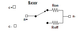
 S-Element Voltage-Controlled Switch Instance Netlist FormatThe S-element voltage-controlled switch is generated for Nexxim by Maxwell SpicelinkÔ. This element has the netlist format: Sxxx n+ n- c+ c- modelname n+ and n- are the positive and negative signal voltage nodes. c+ and c- are the positive and negative control voltage nodes. modelname is the name of a .MODEL statement of type SW elsewhere in the netlist. See the SW Switch Model description for the operation of the switch. S-Element Voltage-Controlled Switch Instance Netlist Examples1 1 2 3 4 switch1 SW Switch ModelThe SW model statement has the following netlist syntax: .MODEL modelname SW [model_parameters] The modelname is the name used by S-elements to reference this model definition. The keyword SW is required for voltage-controlled switch models.
SW Switch Model Netlist Example.MODEL switch1 SW ROFF=1.7 RON=5e+6 VT=5.0 SW Switch Model Notes1. The switch model describes an almost-ideal switch. Properly selected on and off resistances can effectively be zero and infinity by comparison with other circuit elements. 2. The switch is set to ON when [V(c+) - V(c-)] > VT. In the ON state, the resistance from n+ to n- is Ron. The switch is set to OFF when [V(c+) - V(c-)] £ VT. In the OFF state, the resistance from n+ to n- is Roff.
HFSS视频教程 ADS视频教程 CST视频教程 Ansoft Designer 中文教程 |
|
Copyright © 2006 - 2013 微波EDA网, All Rights Reserved 业务联系:mweda@163.com |
|