|
微波射频仿真设计 |
|
|
微波射频仿真设计 |
|
| 首页 >> Ansoft Designer >> Ansoft Designer在线帮助文档 |
|
Nexxim Simulator > Terminal to Differential or Common Mode Converter
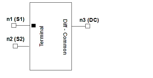
 Selecting Differential or Common Mode ConversionThis component is available for Nexxim schematic designs in Designer. Select the component (SnglNd2DorC) from the lumped_general category of Nexxim components. In the Property window, click on the CoSimulator property to display a menu:
DefaultNetlist or DifferentialMode returns the differential mode on the D terminal. CommonMode returns the common mode on the C terminal. Netlist FormThe netlist generated by this component depends on the CoSimulator selection. With DefaultNetlist or DifferentialMode selected, the terminal to differential pair converter has the following three-line Nexxim netlist syntax: AxxxA n3 0 n1
inet_1 N=2 COMPONENT=transformer1x1 With CommonMode selected, the terminal to common mode converter has the following three-line Nexxim netlist syntax: AxxxA inet_1 0
n3 n2 N=2 COMPONENT=transformer1x1 n1 (S1), n2 (S2), and n3 (D or C) are the nodes connected to the mode converter. The entry COMPONENT=transformer1x1 identifies the underlying transformers (see Notes).
Netlist ExampleA2481A net3 0 net1 inet_1 N=2 COMPONENT=transformer1x1 A2481B net3 0 inet_1 net2 N=2 COMPONENT=transformer1x1 R2481 inet_1 0 25 Notes1. The mode converter incorporates two ideal transformers and a resistor. The single-ended terminals (S1 and S2) are converted to either a differential or a common mode terminal (D or C). 2. The equivalent circuit to extract the differential mode is shown below. Both transformers have 2:1 coupling ratios.
3. The equivalent circuit to extract the common mode is shown below. Both transformers have 2:1 coupling ratios.
HFSS视频教程 ADS视频教程 CST视频教程 Ansoft Designer 中文教程 |
|
Copyright © 2006 - 2013 微波EDA网, All Rights Reserved 业务联系:mweda@163.com |
|