|
 Ansoft Designer / Ansys Designer 在线帮助文档: Ansoft Designer / Ansys Designer 在线帮助文档:
Nexxim Simulator >
Nexxim Component Models >
Offset Stripline Elements >
Multi-Coupled Lines, Differential Pairs, Field Solver
Multi-Coupled Lines, Differential Pairs,
Field Solver


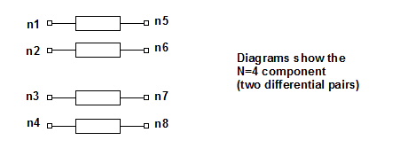
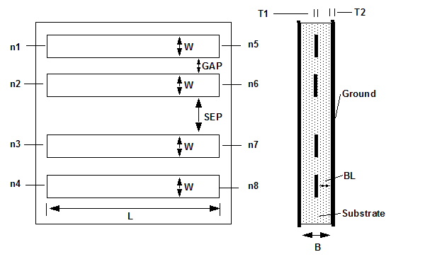
A multicoupled line, two differential pairs, field solver
instance has the following netlist syntax:
Wxxx n1 n2 n3 n4 0 n5
n6 n7 n8 0 N=4 [L=length] FSmodel=modelname
.MATERIAL conductor METAL CONDUCTIVITY=conductivity
.MATERIAL dielectric DIELECTRIC ER=er LOSSTANGENT=losstangent
.SHAPE RECT1 RECTANGLE WIDTH=w HEIGHT=t1 // Conductors
.LAYERSTACK offsetstripline
+ LAYER=(cond1, t2) // Ground plane
+ LAYER=(dielectric, B)
+ LAYER=(cond1, t2)
.MODEL modelname W MODELTYPE=Fieldsolver
+ LAYERSTACK=offsetstripline
+ CONDUCTOR=(SHAPE=RECT1, ORIGIN=(0, 't2 + BL')
+ MATERIAL=conductor, TYPE=SIGNAL)
+ CONDUCTOR=(SHAPE=RECT1, ORIGIN=('w+gap', 't2 + BL'
+ MATERIAL=conductor, TYPE=REFERENCE)
+ CONDUCTOR=(SHAPE=RECT1, ORIGIN=('2w+gap', 't2 + BL')
+ MATERIAL=conductor, TYPE=SIGNAL)
+ CONDUCTOR=(SHAPE=RECT3, ORIGIN=('3w+2gap+sep', 't2
+ BL')
+ MATERIAL=conductor, TYPE=REFERENCE)
n1, n2, n3,
and n4 are the names of the input nodes. n5, n6,
n7, and n8 are the corresponding output nodes. The entry
N=4 shows that this is a 4-conductor,
2-pair differential line.
The entry FSmodel=modelname
identifies the field solver microstrip model.
Note
|
The default values
for the differential coupled lines are the ones assigned when placing
a component from the Ansoft Component library in a schematic. There
are NO defaults for netlist designs; all values must be specified.
|
Netlist Example
W3 Port1 Port2 0 net_1911 net_2 0 N=2 L=0.002 FSmodel=BCL1
.MATERIAL copper METAL CONDUCTIVITY=5.8e7
.MATERIAL dielectric DIELECTRIC ER=4.4 LOSSTANGENT=0.02
.SHAPE RECT1 RECTANGLE WIDTH=.002 HEIGHT=.001 // Conductors
.LAYERSTACK STACK1
+ LAYER=(PEC, .003) // Bottom ground
+ LAYER=(dielectric, .01)
+ LAYER=(AIR, .03)
.MODEL MSFS1 W MODELTYPE=Fieldsolver
+ LAYERSTACK=STACK1
+ CONDUCTOR=(SHAPE=RECT1, ORIGIN=(0, '.003+.01')
+ MATERIAL=conductor, TYPE=SIGNAL)
+ CONDUCTOR=(SHAPE=RECT1, ORIGIN=('.002+.004', '.003+.01')
+ MATERIAL=conductor, TYPE=SIGNAL)
+ CONDUCTOR=(SHAPE=RECT1, ORIGIN=('2*.002+.004', '.003+.01')
+ MATERIAL=conductor, TYPE=SIGNAL)
+ CONDUCTOR=(SHAPE=RECT1, ORIGIN=('3*.002+2*.004', '.001+.01')
+ MATERIAL=conductor, TYPE=SIGNAL)


HFSS视频教程
ADS视频教程
CST视频教程
Ansoft Designer 中文教程
|
|

