|
微波射频仿真设计 |
|
|
微波射频仿真设计 |
|
| 首页 >> Ansoft Designer >> Ansoft Designer在线帮助文档 |
|
Nexxim Simulator > Current-Controlled Switch, SPDT
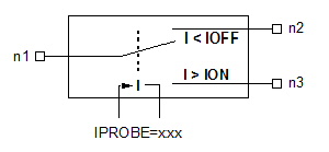
 Netlist FormatAn instance of a current-controlled single-pole, double throw switch has the netlist syntax: Gxxx ( n1 n2 n3 ) ISPDT PROBE=name [ROFF=val] [RON=val] [IOFF=val] [ION=val] [AREA=val] n1 is the input node, n2 is the “OFF” output node, n3 is the “ON” output node, n4 and n5 are the control nodes. The parentheses are required around the list of node names. The entry ISPDT identifies the element as a current-controlled SPDT switch.
Netlist Examplev1 c1 0 SIN(0 10 1e6) // Control source R1 c1 0 1 Vn1 n1 0 10 Rn2 n2 0 10 Rn3 n3 0 10 G1 (n1 n2 n3) ispdt probe=v1 Notes1. In normal operation, ION is greater than IOFF. Output node n2 is selected whencontrol current IC is less than or equal to IOFF, and output node n3 is selected when IC is greater than or equal to ION. 2. In inverted operation, IOFF is greater than ION. Output node n2 is selected when IC is greater than or equal to IOFF, and output node n3 is selected when IC is less than or equal to ION. ISPDT Model EquationsG1 is the conductance betrween node 1 and node 2. G2 is the conductance between node 1 and node 3. If ((ION > IOFF && IC >= ION) || (ION < IOFF && IC <= ION)):


Else if ((ION > IOFF && IC <= IOFF) || (ION < IOFF && IC >= IOFF)):


Else:


Where:


HFSS视频教程 ADS视频教程 CST视频教程 Ansoft Designer 中文教程 |
|
Copyright © 2006 - 2013 微波EDA网, All Rights Reserved 业务联系:mweda@163.com |
|