|
微波射频仿真设计 |
|
|
微波射频仿真设计 |
|
| 首页 >> Ansoft Designer >> Ansoft Designer在线帮助文档 |
|
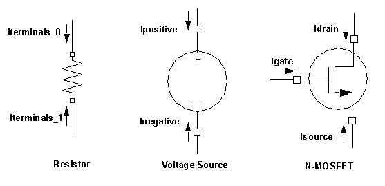
Nexxim Simulator > PRINT Statements with Simple ValuesThe netlist syntax for simple outputs is: .PRINT [analysis] output1 [output2] ... The sections that follow explain the analysis type and the output specifications. Analysis Type The analysis is one of: A .PRINT statement that does not have an explicit analysis is automatically supplied with one using the following rules: • A .PRINT that occurs before ANY analysis is filled in as “.PRINT dc.” • Any other .PRINT statement is filled in with the name of the analysis specified most recently above it. • All .PRINT statements that apply to a given analysis type are then applied to that analysis. So, for example, a netlist that specifies a circuit and then the following: .print V(1) .tran 1e-2 1 .print V(2) .dc sweep R1 100 200 10 .print V(3) .dc sweep R2 100 200 50 .print V(4) will be interpreted as .print dc V(1) .tran 1e-2 1 .print tran V(2) .dc sweep R1 100 200 10 .print dc V(3) .dc sweep R2 100 200 50 .print dc V(4) and will perform three analyses: 1. The transient analysis, in which only V(2) is saved. 2. A DC analysis sweeping the value of R1, in which only V(1), V(3), and V(4) are saved. 3. A DC analysis sweeping the value of R2, in which only V(1), V(3), and V(4) are saved. Output Quantities The output quantities can be node voltages or currents through individual elements. For a node voltage, the syntax is: V(n1) The simulator outputs the voltage difference between the specified node name (n1) and ground. With DC, transient, harmonic balance, and oscillator analyses, the output can specify a differential voltage between nodes, using the syntax: V(n1,n2) The output is the differential voltage for the node pair V(n1) - V(n2). If n1 and n2 are the same node, the output evaluates to zero volts. For a current through a branch containing any single device, the syntax is: I(device_name) The output includes the current entering the device through each node. The following .PRINT statement outputs the current through resistor R10 in a harmonic balance analysis: .PRINT HB I(R10) The outputs would include the current values Iterminals_0(R1) and Iterminals_1(R1) (see illustration below). The following statement outputs the current through voltage source VSRC in a transient analysis: .PRINT TRAN I(VSRC) The outputs would include the current values Ipositive(VSRC) and Inegative(VSRC) (see illustration below). To obtain voltage and current output variables within one or more subcircuit levels, use the following syntax: V(subcircuit1.[subcircuit2.]...[subcircuitn.]element) I(subcircuit1.[subcircuit2.]...[subcircuitn.]element) For example, if subcircuit instance XSUB1 contains voltage source V6, the .PRINT statement to output the current through V6 in transient analysis would be: .PRINT TRAN I(XSUB1.V6) If XSUB1 is an instance of a subcircuit whose definition includes a node N25, the .PRINT statement to output the voltage through node N25 in transient analysis would be: .PRINT TRAN V(XSUB1.N25) If subcircuit instance XSUB1 contains a nested subcircuit instance XSUB2 which in turn includes NMOS MOSFET M23, the .PRINT statement to output the current through D23 would be: .PRINT TRAN I(XSUB1.XSUB2.M23) The outputs would include the current values Isource(M23), Igate(M23), and Idrain(M23). The illustration below shows the directions of the current values for the resistor, voltage source, and MOSFET examples given earlier.
HFSS视频教程 ADS视频教程 CST视频教程 Ansoft Designer 中文教程 |
|
Copyright © 2006 - 2013 微波EDA网, All Rights Reserved 业务联系:mweda@163.com |
|