|
微波射频仿真设计 |
|
|
微波射频仿真设计 |
|
| 首页 >> Ansoft Designer >> Ansoft Designer在线帮助文档 |
|
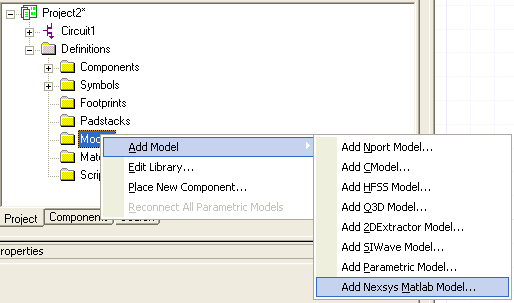
Nexxim Simulator > Creating a MATLAB UDM Component in DesignerTo create a schematic component in Designer for the Nexsys Matlab UDM, follow these steps. 1. In a Circuit design project, right click Models under Definitions. Expand the Add Model tree and select the Add Nexsys Matlab Model tab.
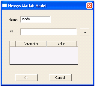
The Nexsys Matlab Model dialog opens.
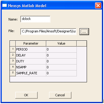
Browse to find the desired .m file in the userlib directory under the Designer installation directory. After the model file has been selected, its parameter list will be displayed.
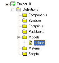
Click OK. The MATLAB UDM (dclock in this case) appears in the Models list.
Place the model in the design by clicking on it and selecting Place New Component.
HFSS视频教程 ADS视频教程 CST视频教程 Ansoft Designer 中文教程 |
|
Copyright © 2006 - 2013 微波EDA网, All Rights Reserved 业务联系:mweda@163.com |
|