|
微波射频仿真设计 |
|
|
微波射频仿真设计 |
|
| 首页 >> Ansoft Designer >> Ansoft Designer在线帮助文档 |
|
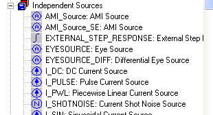
Nexxim Simulator > Add an External Step Response to a QuickEye AnalysisInstead of having Nexxim compute the step response, you can supply the step response via a data file, using the External Step Response Nexxim source. First, place Eye Sources and Probes in the circuit. Select the External Step Response from the Independent Sources list on the Components tab:
The External Step Response component does not physically connect to the circuit. Click on the component to open the Properties list:
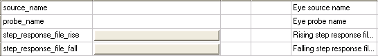
Select the source name and the probe name. The source and probe names appear automatically when they are present in the circuit. Each step response source applies to one source and one probe. Specify the files that contain the rising and falling step responses by clicking the buttons in the value field. The same dialog applies to both files:
If only one file is supplied, the rise and fall are treated as symmetrical.
The step response data files have a two-column format: time voltage. Linear interpolation is used between time points.
HFSS视频教程 ADS视频教程 CST视频教程 Ansoft Designer 中文教程 |
|
Copyright © 2006 - 2013 微波EDA网, All Rights Reserved 业务联系:mweda@163.com |
|