|
微波射频仿真设计 |
|
|
微波射频仿真设计 |
|
| 首页 >> Ansoft Designer >> Ansoft Designer在线帮助文档 |
|
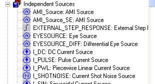
Nexxim Simulator > Add a QuickEye Source to a SchematicThe Eye Source may be selected from the Independent Sources list on the Components tab:
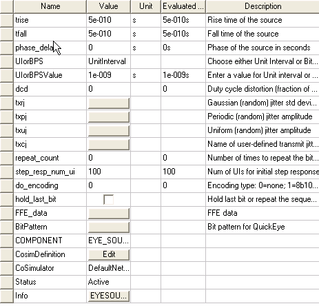
Both single-ended and differential versions are available. In a schematic, click on the Eye Source to display the Properties window:
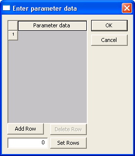
For QuickEye analysis, all Eye Source parameters apply: • The resistance to be placed in series with the eye source. The default is 50 Ohm. • The logic low, vlow. The default is 0 volt. • The logic high, vhigh. The default is 1 volt. • The risetime of input (vrise). The default is 5.0e-10 seconds (500 picoseconds). • The falltime of input (tfall). The default is 5.0e-10 seconds (500 picoseconds). • The phase_delay for this source. The default is 0 seconds. • The data rate: Use the UIorBPS pulldown to select UnitInterval or BitsPerSecond. Then use the UIorBPSValue field to enter the unit interval size or number of bits per second. • The duty cycle distortion (dcd) value is a fraction of UI between 0 and 1. The default is 0. For txrj, txpj, and txuj, clicking the Value button allows you to specify one or more values, generating multiple jitter sources:
• For the random transmit jitter (txrj) the value is the standard deviation for the Gaussian distribution. The default is 0 seconds. • For the Periodic random transmit jitter (txpj) the value is the amplitude. The default is 0 seconds. • For the Uniform random transmit jitter (txuj) the value is the amplitude. The default is 0 seconds. • For the User-defined transmit jitter (txcj) the value is the name of the file containing the time (seconds and probability density function (PDF) data. There is no default.
• The number of unit intervals to be used in computing the step response (step_resp_num_ui). The default is 100.
• To enable Feed-Forward Equalization, set the Number of taps in the FFE field to a positive, non-zero value. The default is zero taps (no FFE). When one or more taps have been specified, the list of tap numbers and locations appears. • By default, Tap 1 is at location 0, the current UI. Use Location Start to set Tap 1 to a positive or negative location. Taps at positive locations are postcursors. Taps at negative locations are precursors. The location of the taps in the display change to reflect the selected starting location. (Click the Reset button to restore the default starting location.)
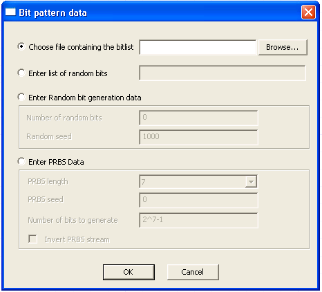
• To specify the tap weights, select Specify and enter the weights. The default is to have Nexxim calculate the weights. The algorithm always places the largest tap weight at location 0. • By default, normalization is performed such that the sum of the absolute values of all the weights is equal to one. Optionally, uncheck the Normalize FFE weights checkbox to disable normalization. • Use the pulldown to select a Compute Ref Probe. When FFE has been enabled, this field is required. A channel can have multiple probes, but only the probe actually at the receiver should be the reference probe. • For more information on FFE, see Feed-Forward Equalization. • Click OK to close the FFE_data dialog and return to the Properties window. • Click on the Bit Pattern button to open the dialog:
Select one of these methods for generating the QuickEye bit pattern. To link to a file with the bit values, click on the Choose file button, then use the Browse dialog to locate and select the data file. To specify a bitlist, click the Enter list button and type in the list of 1s and 0s. To generate a random sequence of bits (instead of the bitlist or bitfile), click the Enter random button. Enter the number of bits and the seed value. To generate a pseudorandom sequence of bit patterns of various lengths, click the Enter PRBS Data button. Use the pulldown to select the length of the pattern, PRBS_length, (2 to 31 bits). Enter a PRBS seed value, and specify the total number of bits to be generated. To invert the PRBS bit stream, check the checkbox at the lower left of the PRBS Data panel. Click OK to close the Bit pattern dialog and return to the Eye Source parameter list.. • To specify one or more repeats of the bits in the bitlist, bitfile, random sequence, or PRBS, set the repeat_count parameter on the Eye Source to the number of repeats. • The do_encoding parameter controls 8b10b or 64b66b encoding of the transmitted bitstream. The default is no encoding (do_encoding=0). To enable 8b10b encoding, set do_encoding to 1. To enable 64b66b encoding, set do_encoding to 2. • The Hold Last Bit checkbox is for crosstalk analysis. When an aggressor’s bit stream is shorter than the victim’s bitstream, the aggressor’s bitlist can be repeated or the last bit value can be held for the duration of the victim’s bitstream. The default is to repeat (checkbox not checked).
HFSS视频教程 ADS视频教程 CST视频教程 Ansoft Designer 中文教程 |
|
Copyright © 2006 - 2013 微波EDA网, All Rights Reserved 业务联系:mweda@163.com |
|