|
微波射频仿真设计 |
|
|
微波射频仿真设计 |
|
| 首页 >> Ansoft Designer >> Ansoft Designer在线帮助文档 |
|
Layout Editor User Guide > Cutout SubdesignCutout Subdesign creates a new subdesign from extracted data by cutting out a portion of a Layout using a selection polygon and/or a net selection. Click on the subdesign name to rename the new design. The original design is not affected by this operation. • If a polygon is selected before the operation is performed, it becomes the default extent polygon. • If the selection is to be entirely by net, then no geometry should be selected before invoking the operation. If multiple polygons are selected, the union of these polygons forms the extent. • If no data is selected (i.e., there is no selection polygon and nothing has been selected in the net table) then a new design is created with a stackup identical to the source design, but no geometry is transferred. Note, however, that “filter geometry by net” must also be selected. • “Cutout Subdesign” will work on hierarchy and footprints, however, everything is “flattened” into the sub-design that is created.
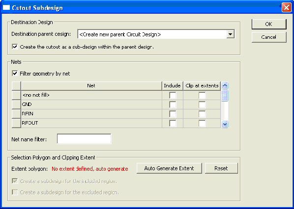
Select Layout > Cutout Subdesign to open the cut out dialog:
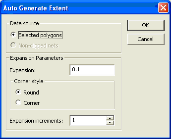
• Destination parent design: From the pulldown list, select an existing top-level design or use "Create new parent Circuit Design" or "Create new parent EM Design". Only top-level designs with a stackup that matches the source design appear in the drop-down list. If a new design is created, it takes its name from the original source design. • Create the cutout as a sub-design within the parent: When selected, data is copied to a new sub-design within the parent; otherwise, the extracted data is inserted into the top-level design. • Filter geometry by net: When selected, the net data is used to control the data selection and clipping; otherwise, the data in the net table is completely ignored. • Nets: — Net: The name of the net. <no net fill>: Refers to polygon data without a net association. <no net trace>: Refers to trace geometry (wide-line or plugin) without a net association. — Include: When selected, the net is included in the data transferred. — Clip at extents: When selected, the net is clipped against the extent polygon. • Net name filter: Limits the data displayed in the net table. Use the filter to build up a selection of nets. The filter has no affect on the final outcome of the operation. For example, if "Y" is entered, only those nets beginning with the letter "Y" are displayed; if "C*0" is entered, then all nets matching the wild-carded pattern are displayed. Nets that are not visible retain their "include" and "clip" settings. • Extent polygon: Name of the extent polygon. • Reset: Resets the extent polygon back to the original polygon; if there was no original polygon, then reset clears the auto-generated polygon. • Create a sub-design for the included region: Only applicable if you are creating a sub-design within the top-level design and after an extent polygon has been defined. This option represents the typical use of the Cutout Subdesign tool. The sub-design inserted into the top-level design consists of the data contained within the extent polygon (and filtered by the net selection). All geometry within the nets that is designated as "clipped" will be truncated at the boundary of the extent polygon. • Create a sub-design for the excluded region: Same as the previous option, however, the sub-design will contain the data outside of the extent polygon, filtered by the net selection and clipped as necessary. It is possible to select both options; in which case two sub-designs are created: one of data within the extent and the other of data outside of the extent. • Auto Generate Extent: Displays a second dialog that permits one to create an extent polygon derived either from the non-clipped nets selected or the current extent polygon. The auto-generated polygon is displayed in the Layout (though it may be difficult to see). It is possible to execute this option as many times as one wishes, adjusting the parameters as needed.
• Data source: The auto-generated extent can use either the current polygon selection or the non-clipped nets as the basis for generating a new extent polygon. • Expansion: The auto-generated extent polygon is simply an expansion of the selected data source; the expansion is either a factor (unitless fraction) of the overall source polygon extent or an absolute offset (e.g. 1mm, 20um). • Corner style: The type of corner to insert in the expanded polygon. Where a "corner" (the simple intersection of the offset edges) can result in rather poor results if there are acute or near-acute angles in the source polygon. • Expansion increments: At times, a single, large offset can generate a poorly formed polygon (a preview of the resulting polygon can be observed in the Layout window). The suitability of a polygon is entirely subjective. However, you can improve the general quality of a polygon by breaking up the expansion into a series of steps (increments of 2, 3, 4, etc.). Such increments represent the number of iterations used to reach the full expansion distance. To improve the general quality of a polygon, the number of increments need not be large; you can start with a small number and increase them as necessary. However, it is important to understand that increasing the number of iterations will also increase the time to compute the expansion. So obviously, a very large number of iterations would have a significant impact on computation time.
HFSS视频教程 ADS视频教程 CST视频教程 Ansoft Designer 中文教程 |
|
Copyright © 2006 - 2013 微波EDA网, All Rights Reserved 业务联系:mweda@163.com |
|