|
微波射频仿真设计 |
|
|
微波射频仿真设计 |
|
| 首页 >> Ansoft Designer >> Ansoft Designer在线帮助文档 |
|
Dynamic Links and Solver On Demand > Transmission Lines Based on HFSS DataA parameterized two port transmission line can be created in Designer based on an HFSS port solution. The characteristic impedance and propagation constant from a port in an HFSS design will be used along with a user input length to generate an S parameter matrix in Designer for a single mode transmission line. The resulting transmission line can be used like any other Designer component in the schematic editor. To generate a transmission line based on an HFSS port solution, first add an HFSS design to a circuit or Nexxim schematic, then on the Project menu, point to Add Model, and then click Add HFSS Model. The HFSS Dynamic Link dialog opens.
Browse to the HFSS design that you want to use and choose the port for the propagation constant and characteristic impedance. On the Link Description tab, select the “Transmission line model” checkbox.
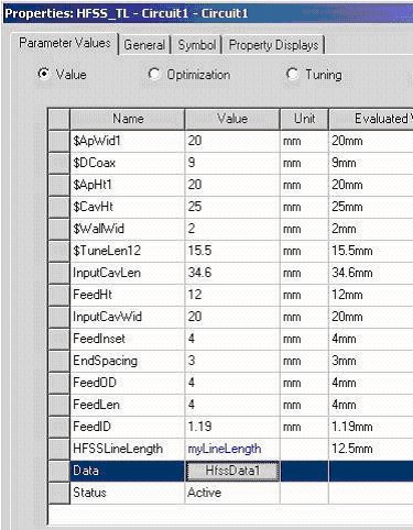
When you click OK a symbol is generated for the schematic:  The properties of this component will include all the properties from the HFSS model plus one called “HFSSLineLength”:  The variable “myLineLength” was created in Designer to vary the length of the transmission line. Designer creates a single mode transmission line using the characteristic impedance and propagation constant from the HFSS design. The length of the line is “HFSSLineLength.” Port solution data from HFSS as a function of design parameters will be either interpolated or solved automatically depending on the status of the “Interpolate missing solutions/Simulate missing solutions” radio button.
HFSS视频教程 ADS视频教程 CST视频教程 Ansoft Designer 中文教程 |
|
Copyright © 2006 - 2013 微波EDA网, All Rights Reserved 业务联系:mweda@163.com |
|